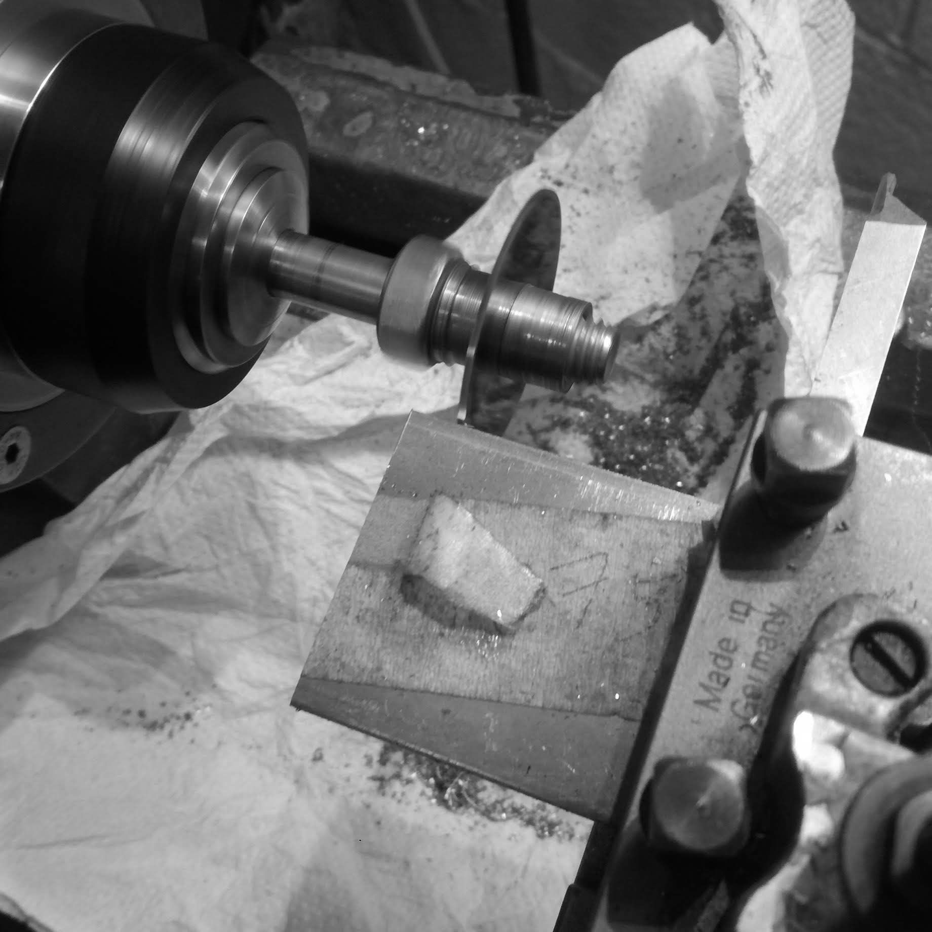
For the dial I start with a raw piece of 316L billet. This dial of course will be solid stainless like the case.
The billet is faced off so that the surface is parallel.
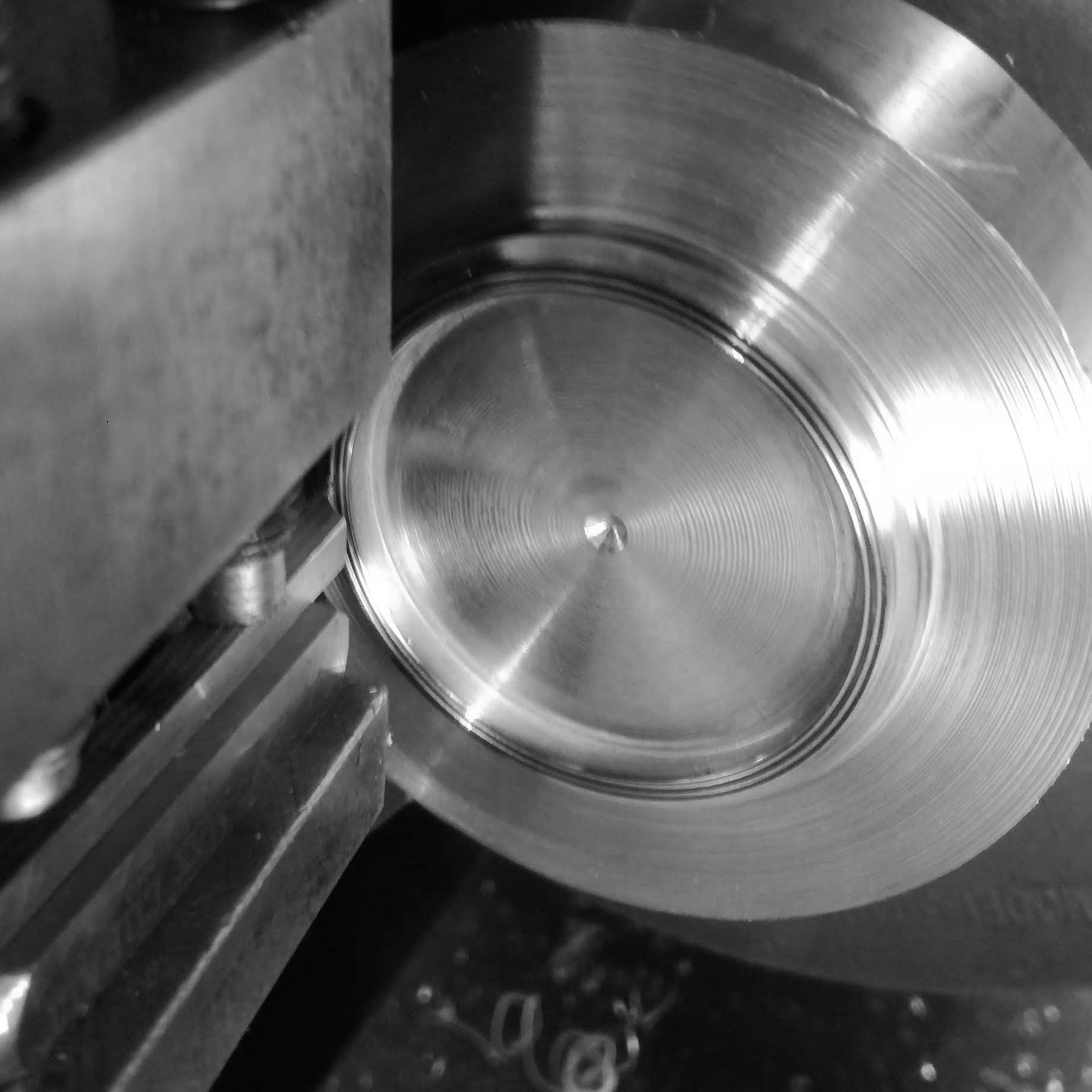
Then the outer and interior dimensions of the dial, as projected, are turned.
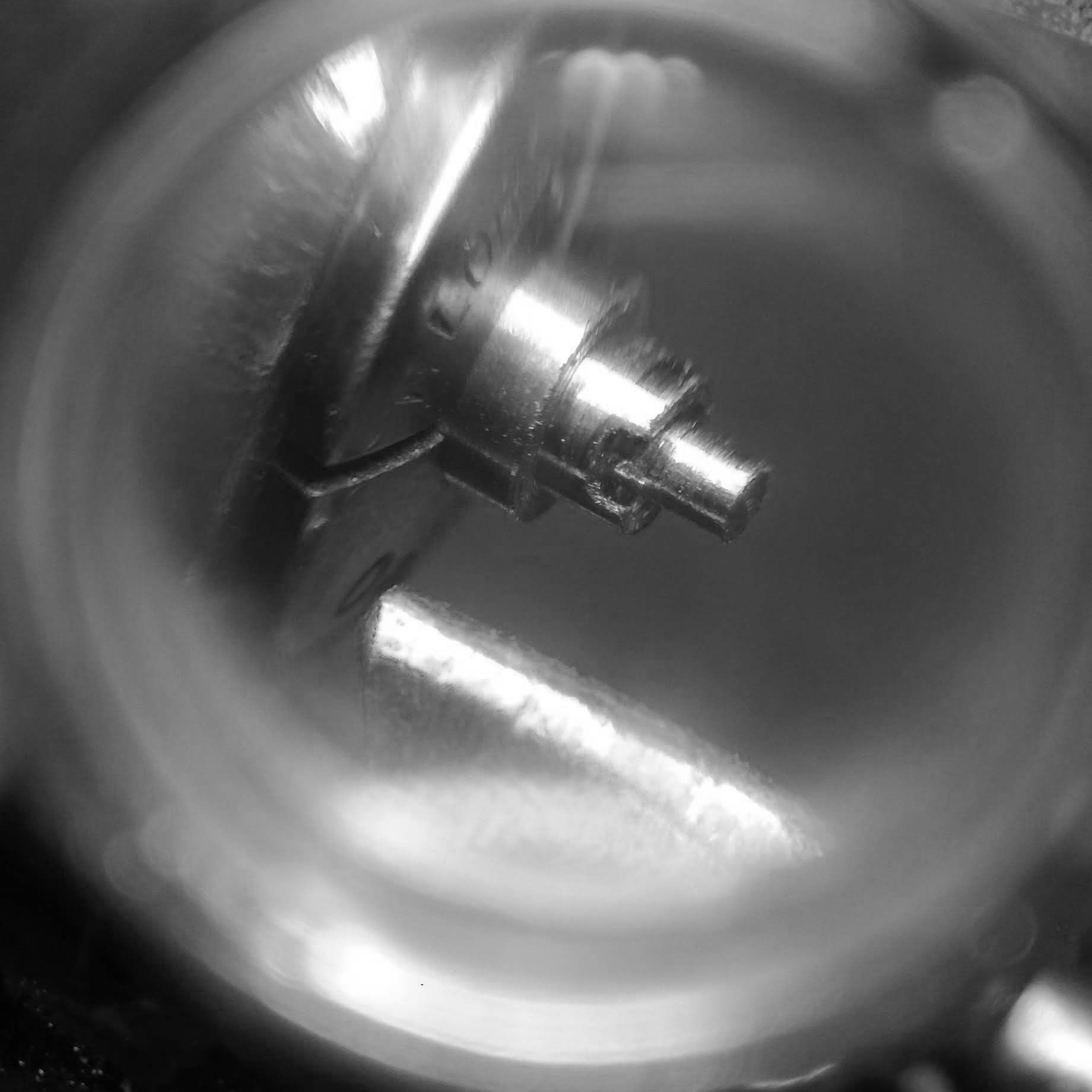
Here I test the fit of the bezel, as the dial will fit inside the bezel to create a more architectural effect on the dial side.
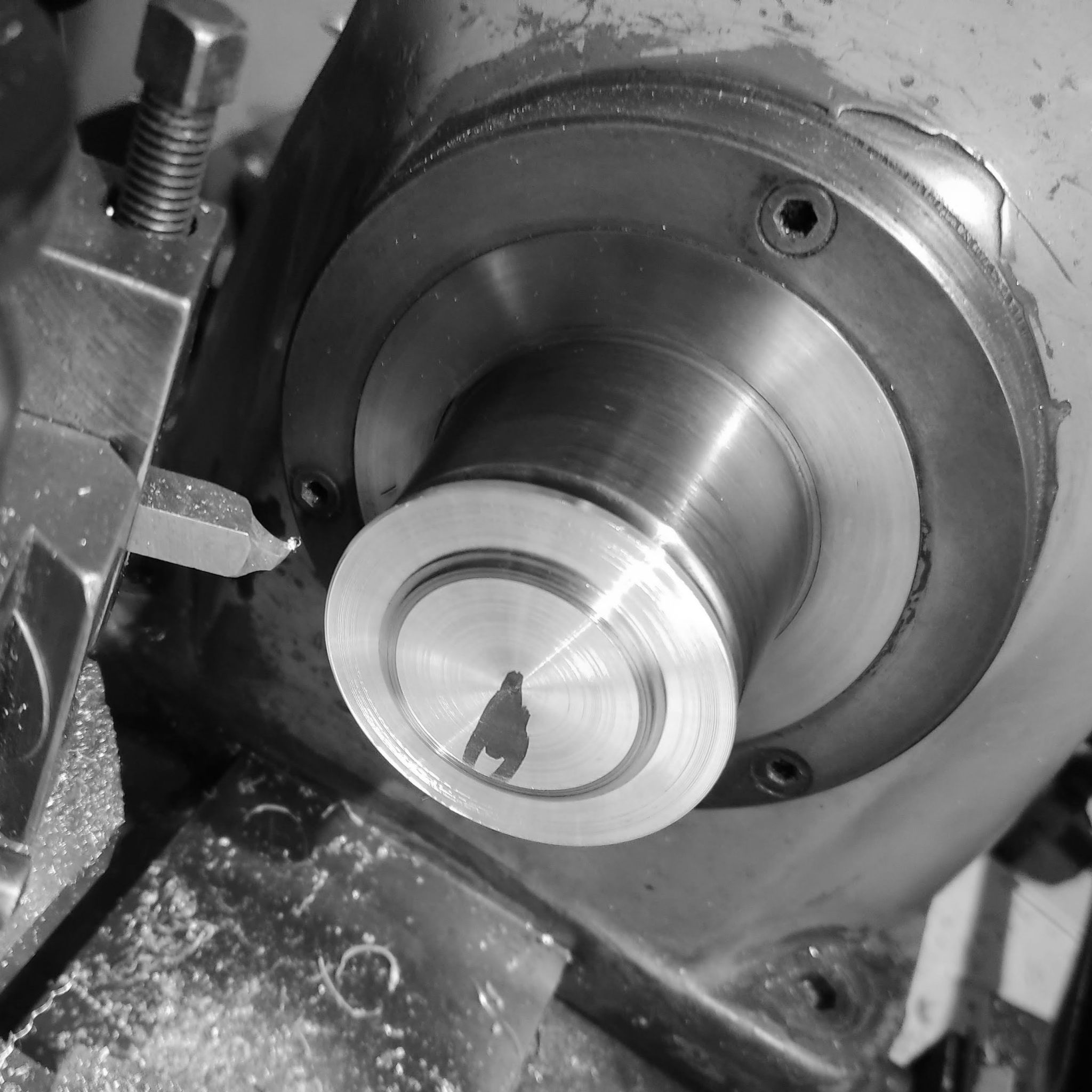
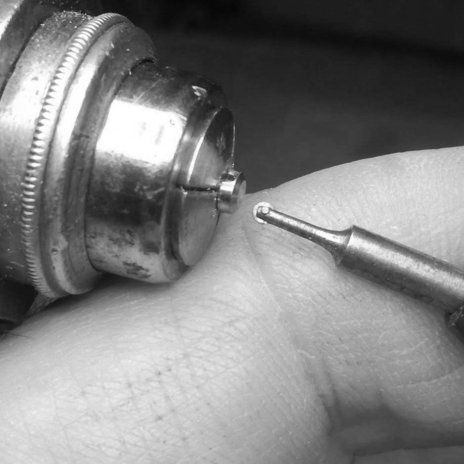
Further adjustment of the dial surface with a cutter that allows to cut into the corners, so that the dial can seat properly against the bezel.
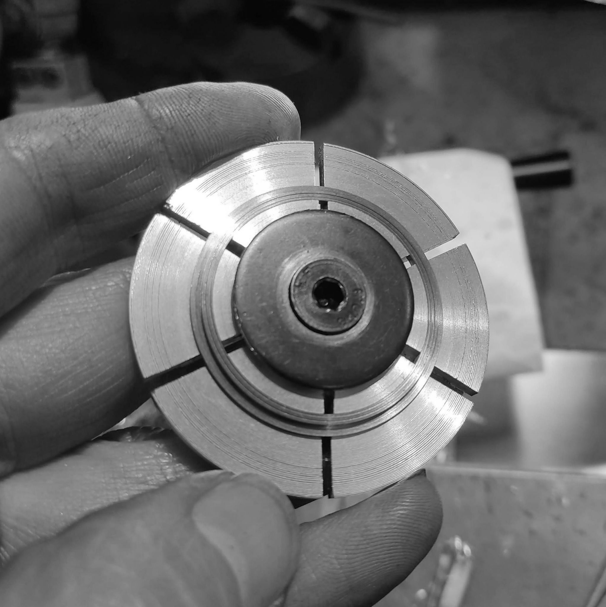
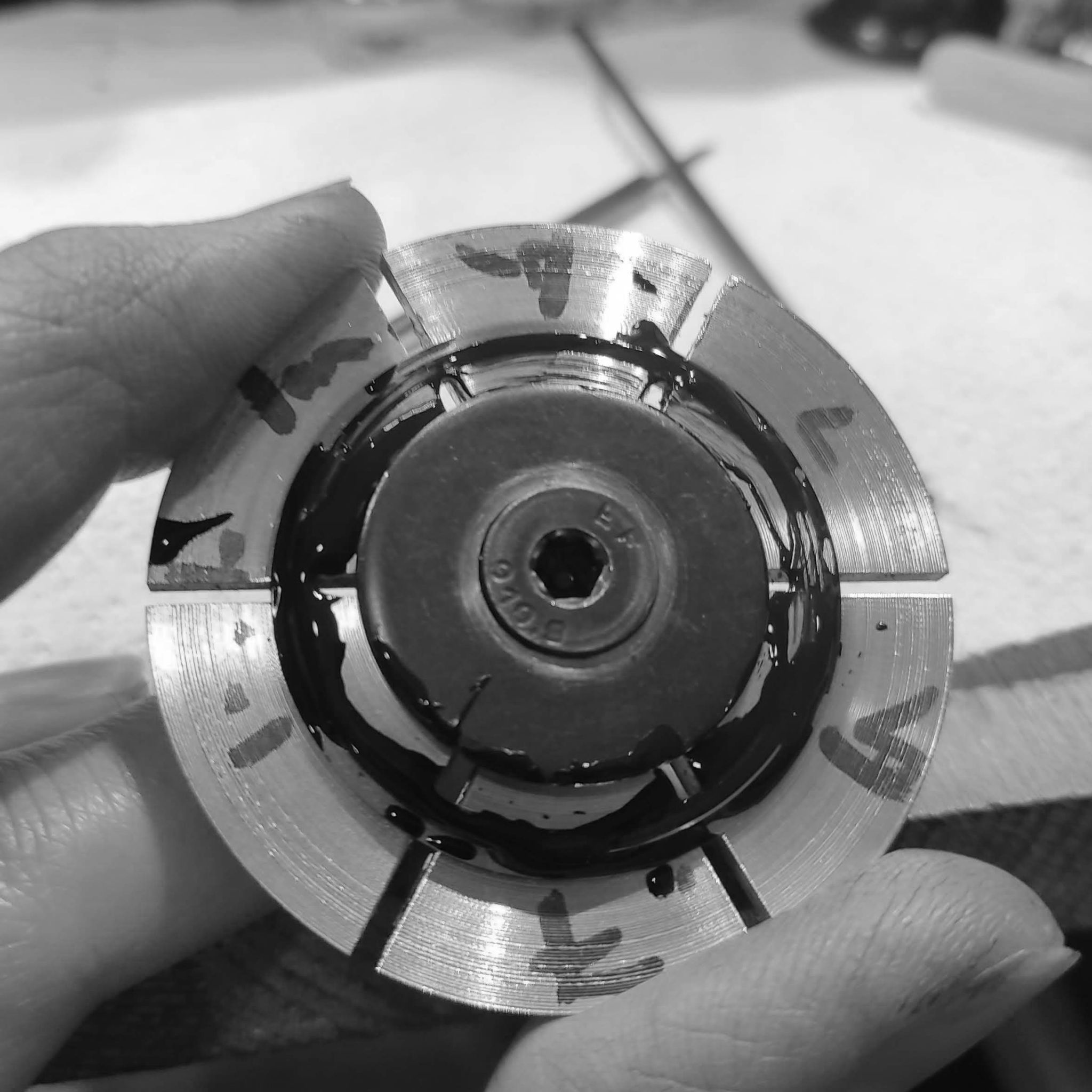
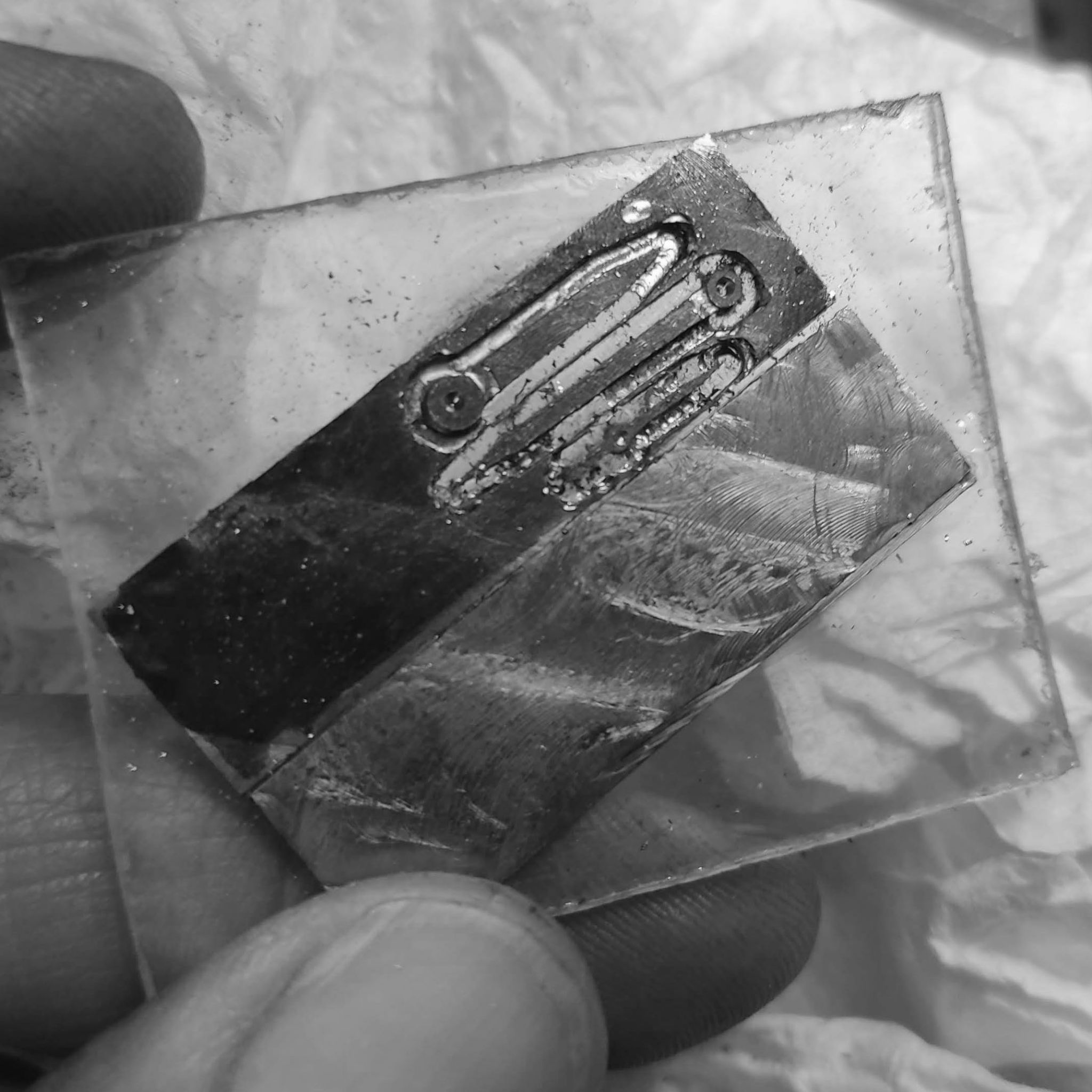
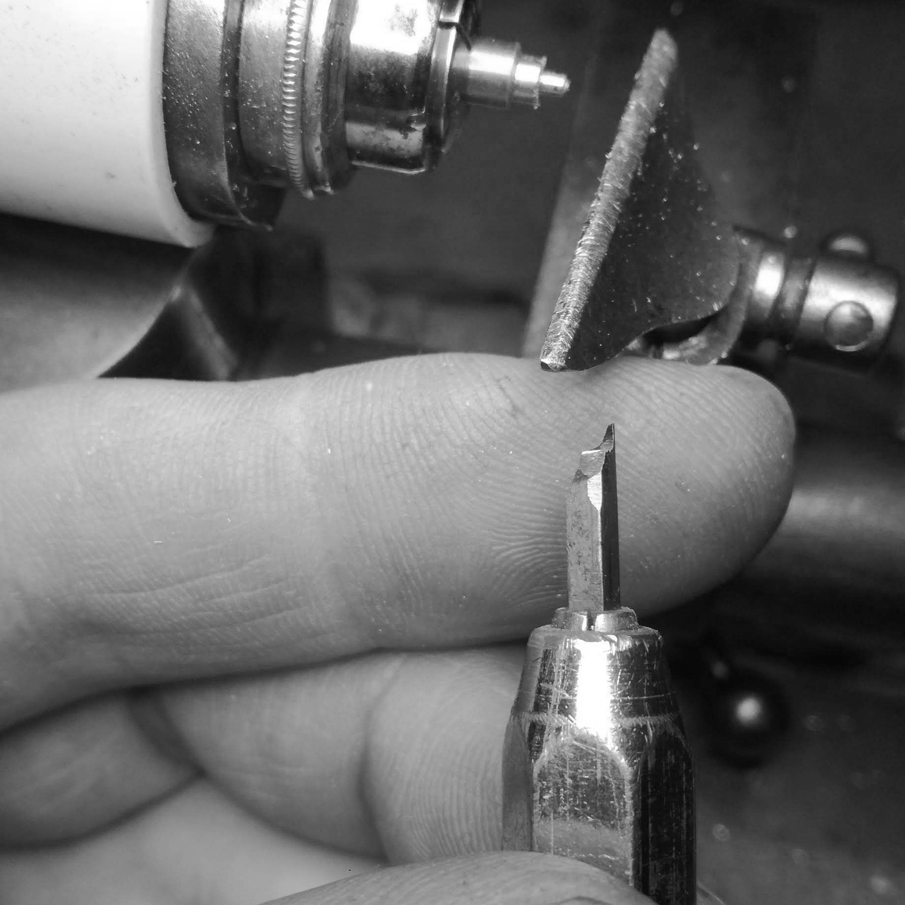
With a 0.2mm wide cutter, specially shaped for this dial, I cut the two groves forming the outer portion of the 'railroad' track.
Further view of how the 'tracks' look like.
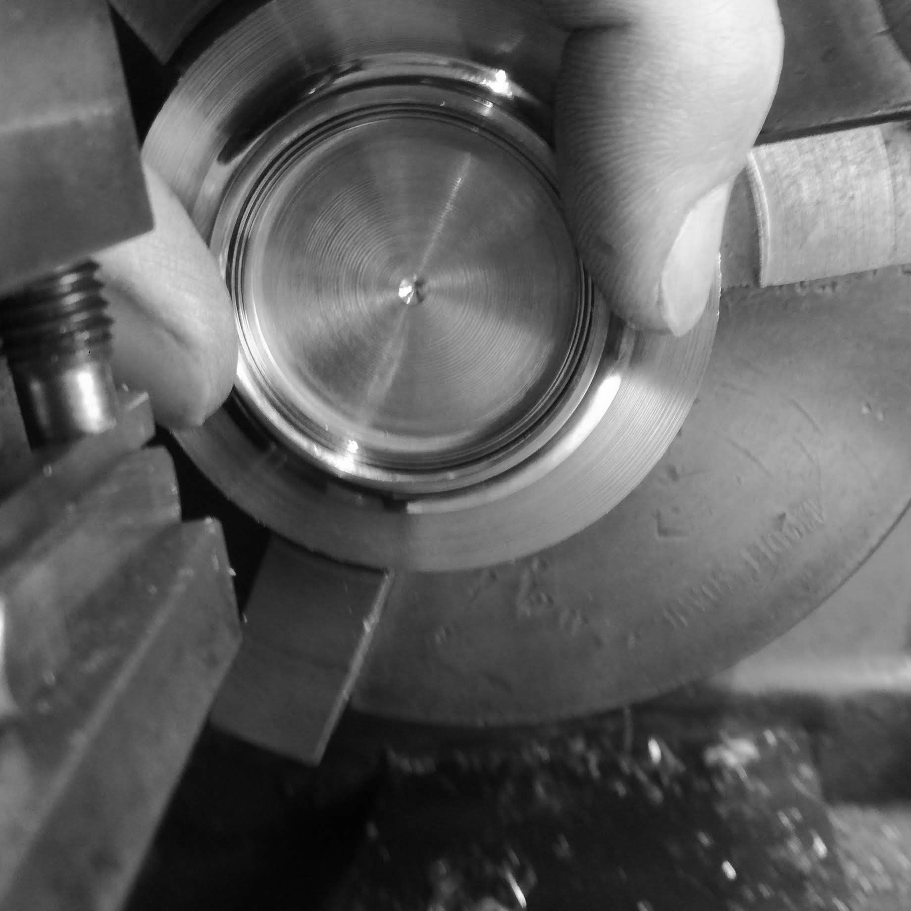
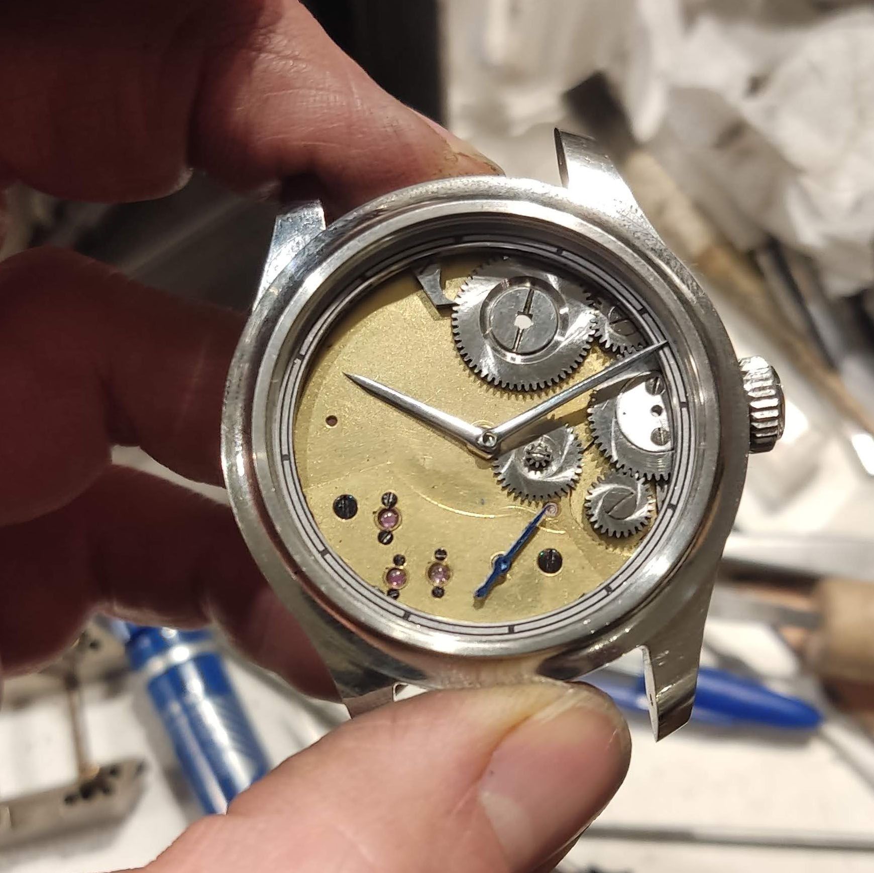
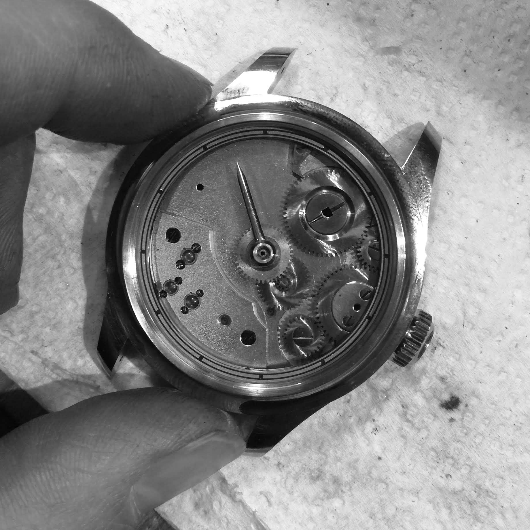
A look at how it will look with the bezel on.
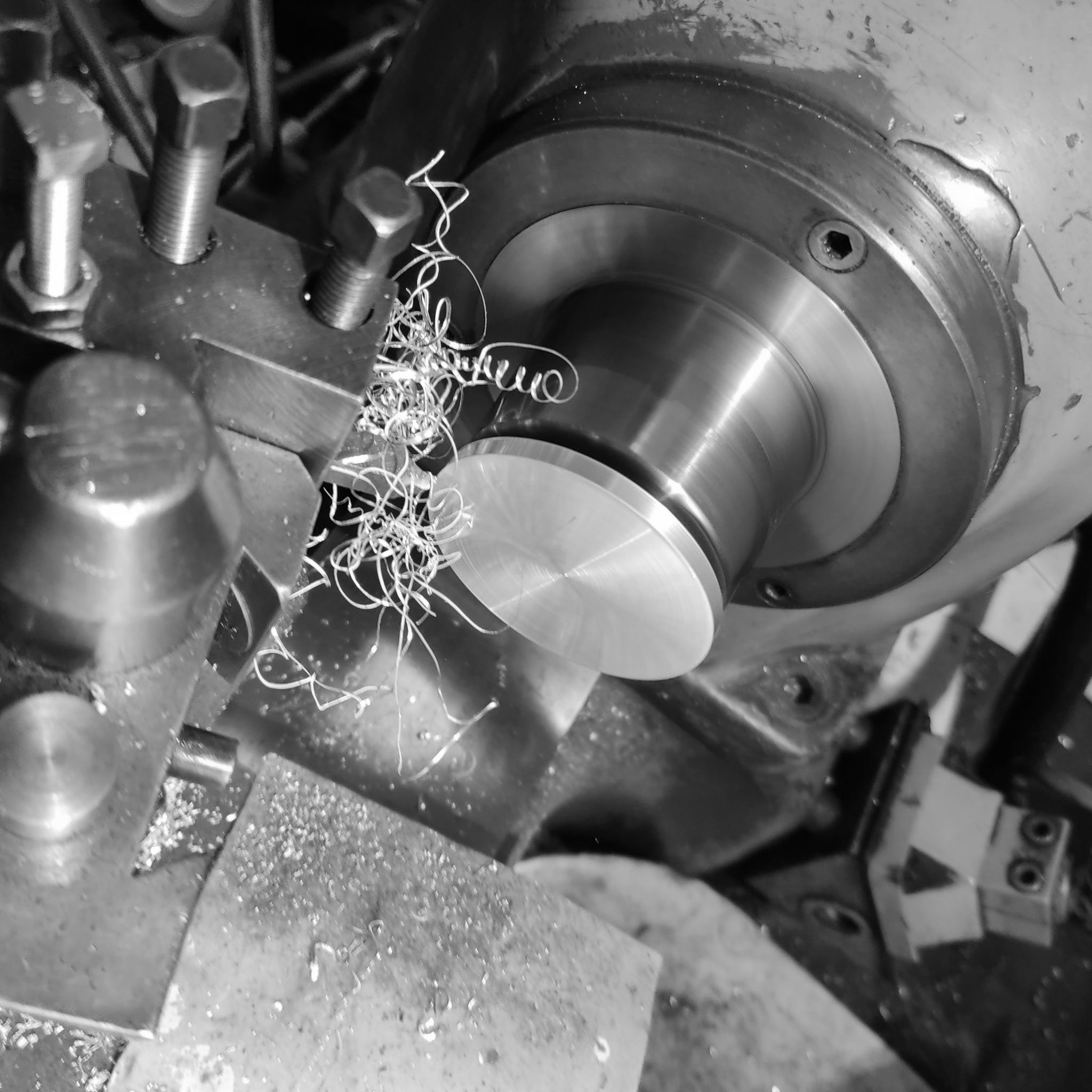
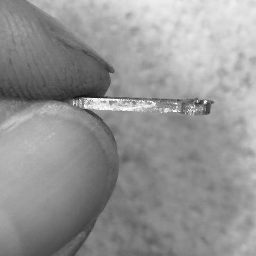
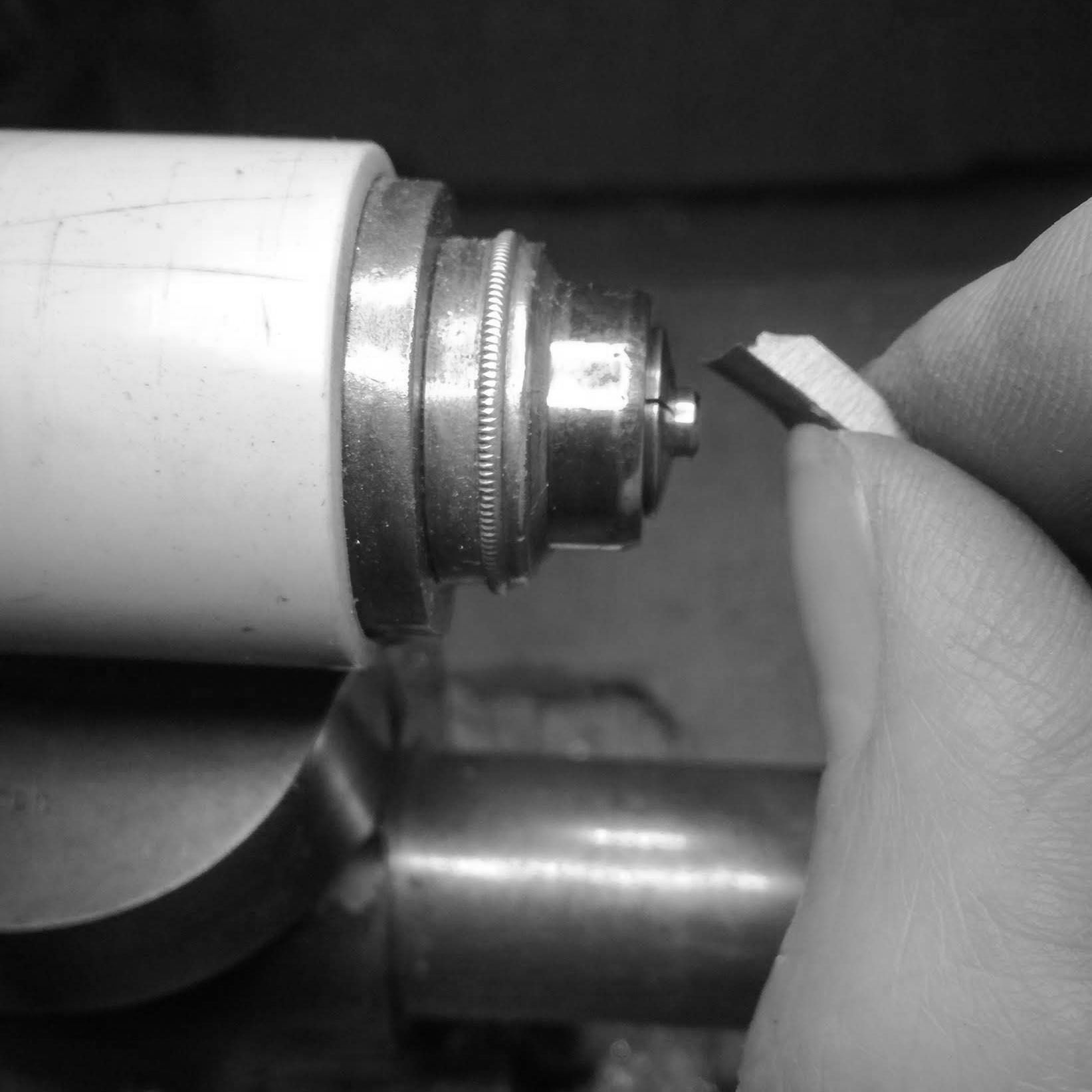
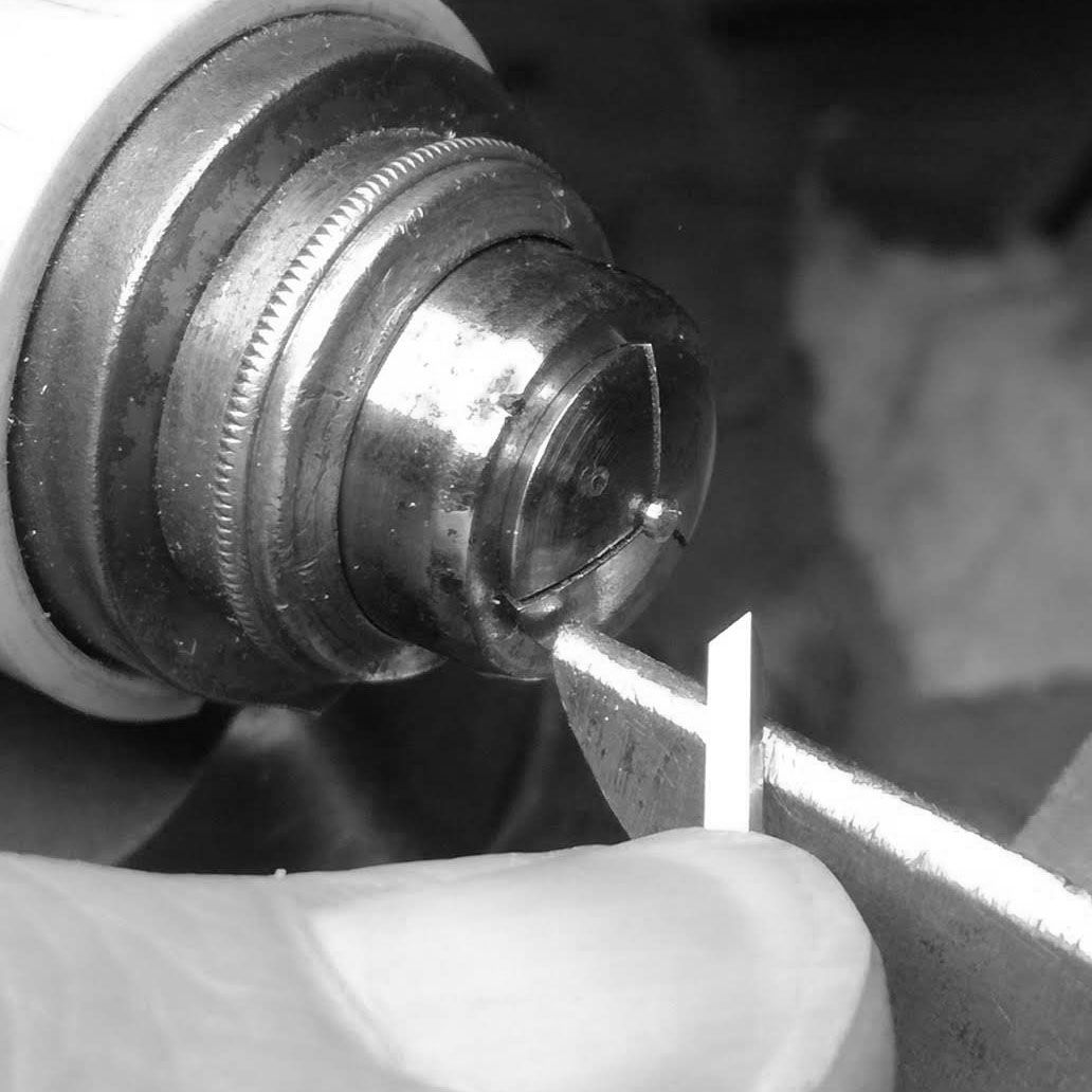
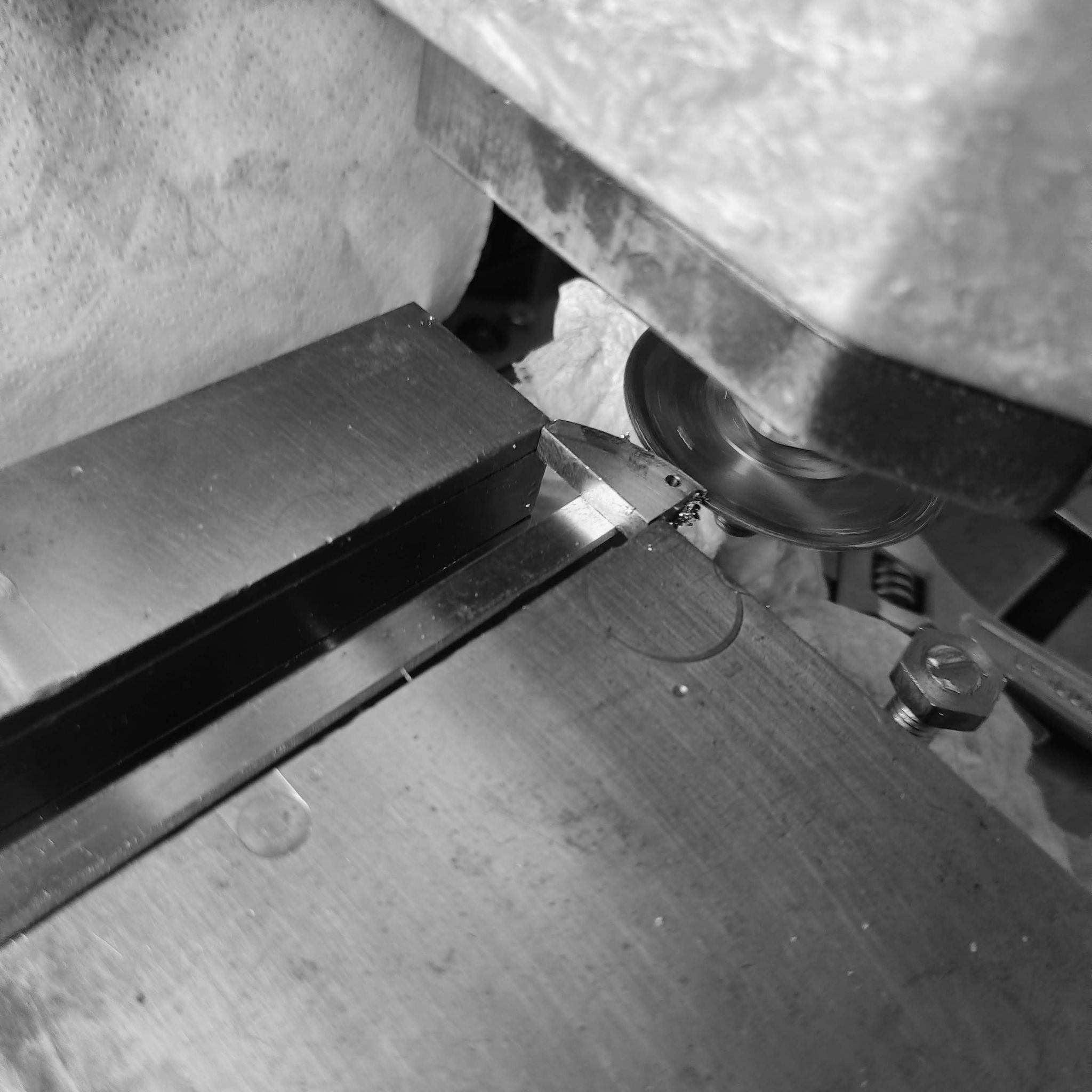
Now a careful operation is done, where I part the dial off. I have to cut slowly to prevent from heat building up, and warping the thin dial.
The lip that holds locates the dial is 0.45mm thick. So it is important that very little heat builds up.
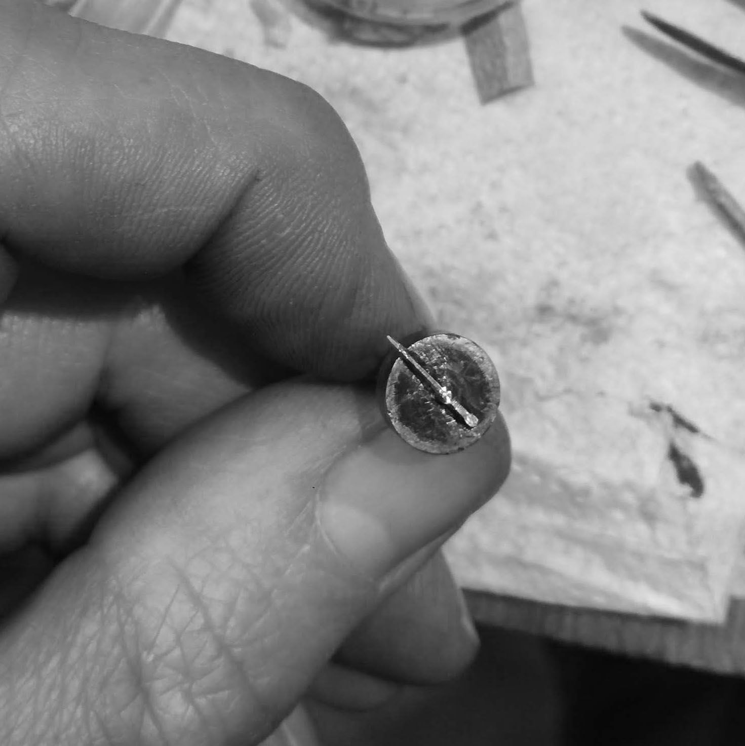
The dial parted off, and resting on the swarf made by the parting off blade.
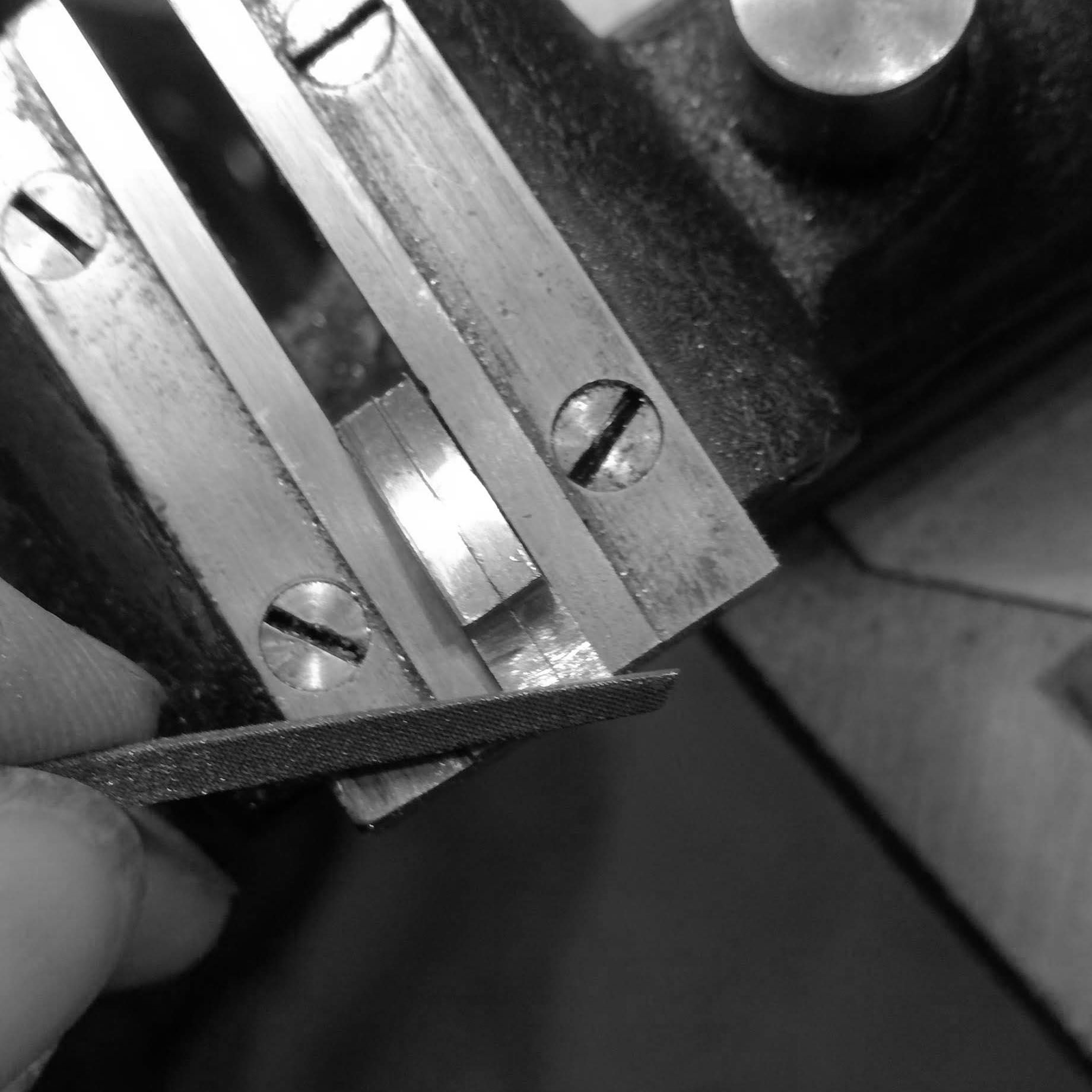
Using a ruby file to take off the burr that is left on the interior of the dial ring from parting off.
In order to hold the dial to mil the 12 index markers, I need to build a jig. This is done from aluminum billet.
The back of the billet is cut first, so that I can turn the diameter of the interior portion of the bezel, and it will be concentric with the holding pin. Here it is being parted off.
The small jig is now faced for parallelism.
The jig was marked with a rough measure of the interior of the dial diameter, and then a step cut.
The interior of the jig was drilled and tapped to accept a M6 screw, that will act, with a piece of steel, to expand the jig jaws.
A thick washer is cut at an angle to act as jaw opening plug for the jig.
The washer sitting on the jig.
The face of the jig is then sliced into six sectors so that it will be elastic.
The jig is then finished to take out the burs and warping that takes place during machining.
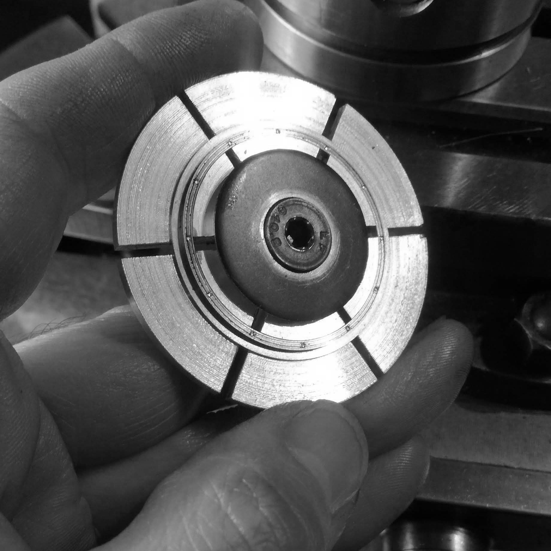
The dial being held by the expanding collet jig. The center screw is tightened, forcing the jaws outwards, and securely holding the dial.
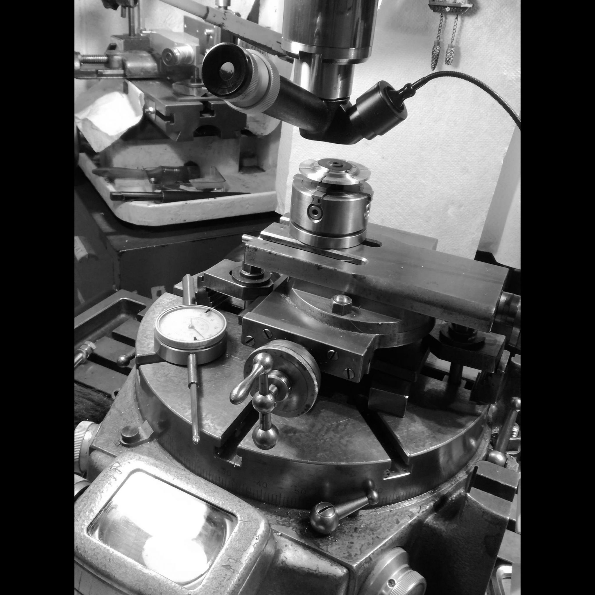
The jig borer rotary table is then centered to the axis of the spindle's rotation.
Then, the jig placed in a chuck, and on a cross slide is positioned until the outer diameter of the dial is centered with the spindle.
I then move the X a-xis to the center of the dial's 'track' and check the proper concentricty of rotation when the centering microscope.
There are 12 divisions of the 360 degrees, so with the precision optical rotary table (precise to 1 second) I index the 12 positions after each marker is drilled.
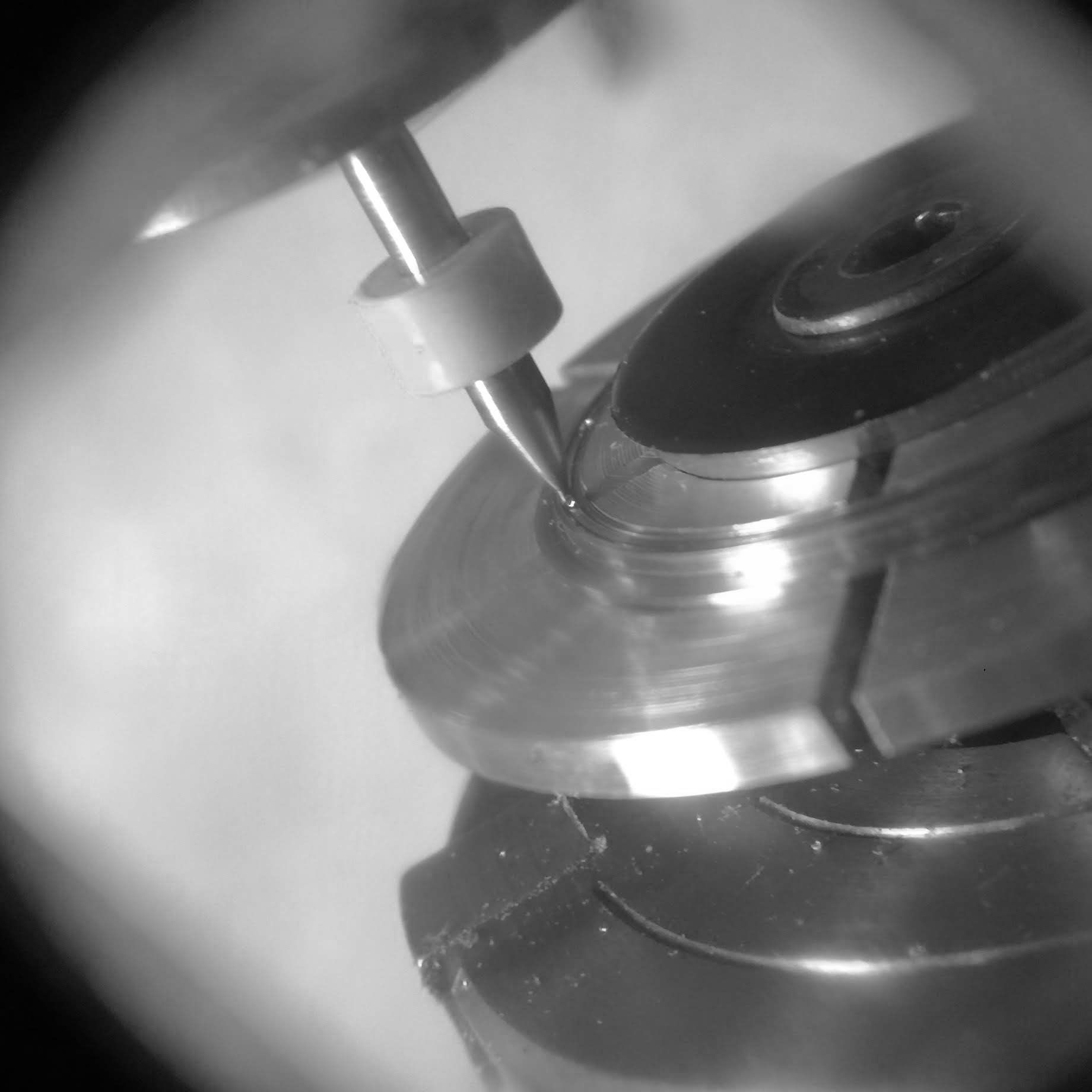
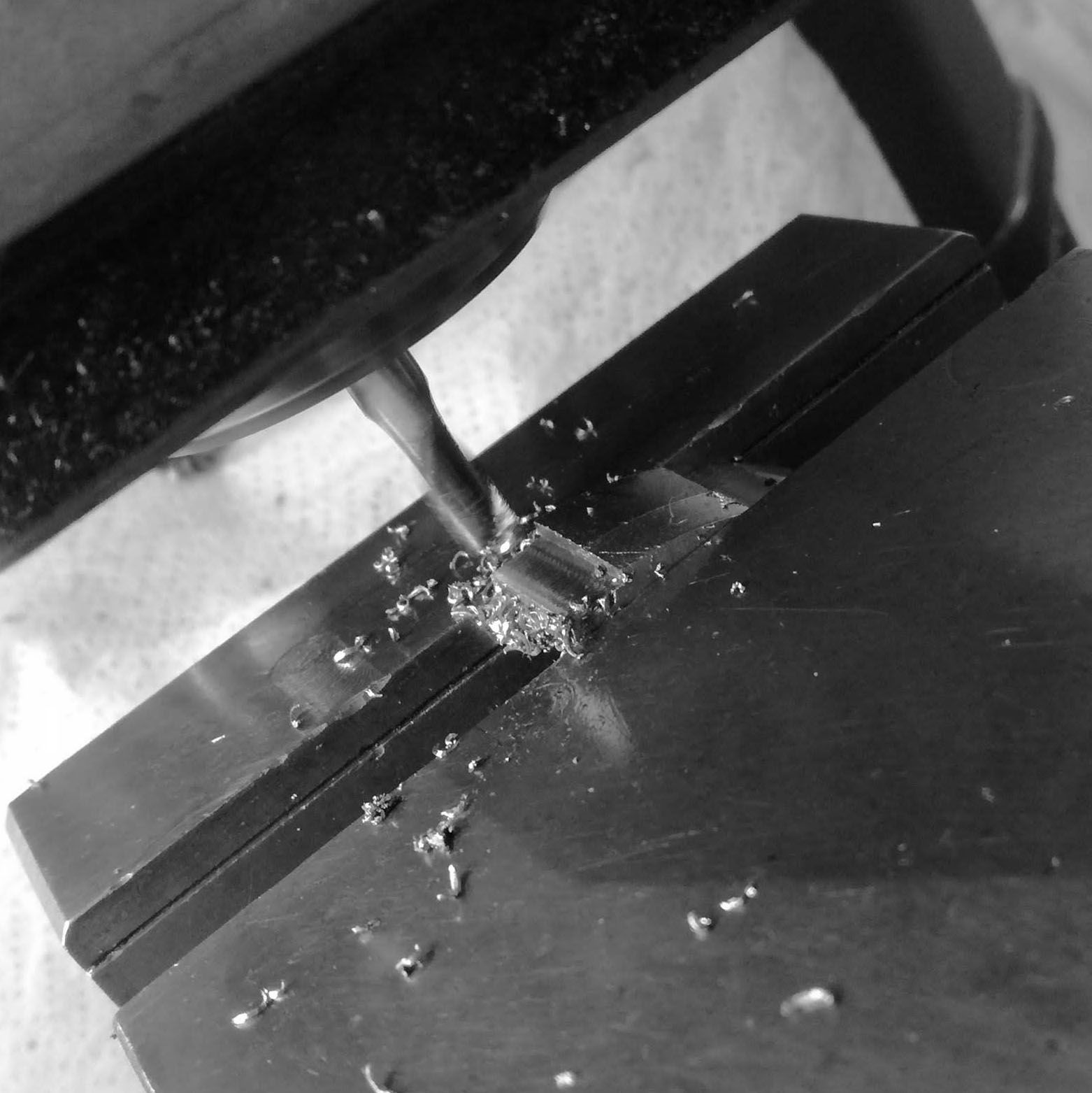
The space between the two tracks is 0.4mm, so a specially purposed short 0.6mm drill is used to make the markers. As milling 0.2mm on stainless risks creating a burr that ruins the dial tracks.
The 12 index markers are drillled.
However, lots of hand work is required because, as can be seen, the burr on this small hole is significant.
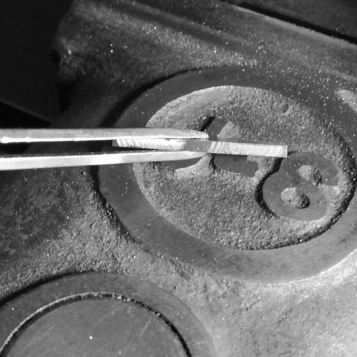
I use the cutter for the tracks as a hand graver to slowly and carefully remove burs. I will use a graver to cut the sides of the index square to the interior of the track.
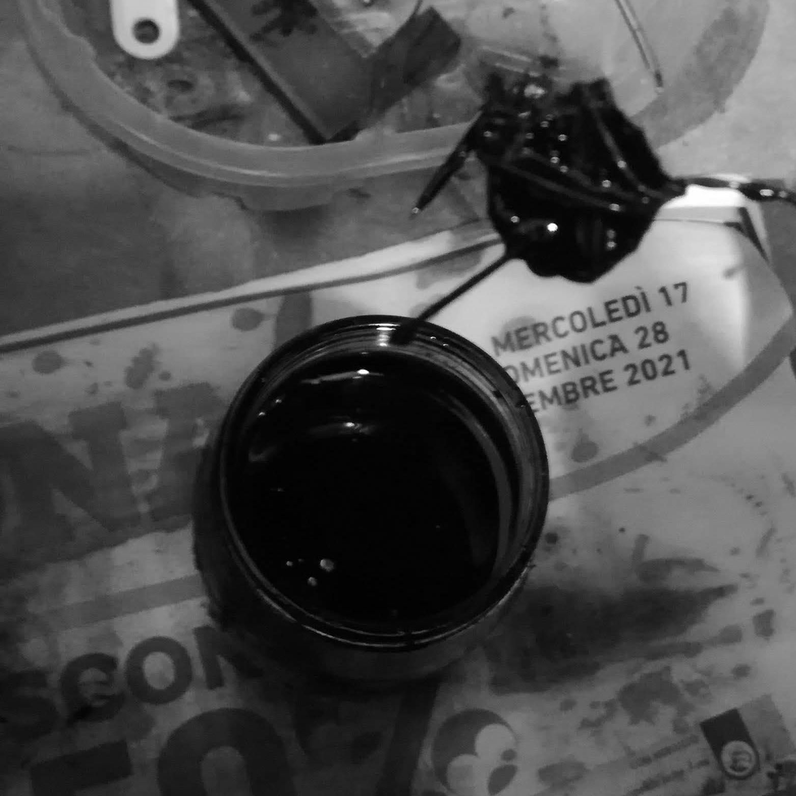
After I cleaned out all the milling marks from the indexes, I started to fill recess with cold enamel. I do this over various days, so that the enamel fills up the space and it is even with the surface of the dial.
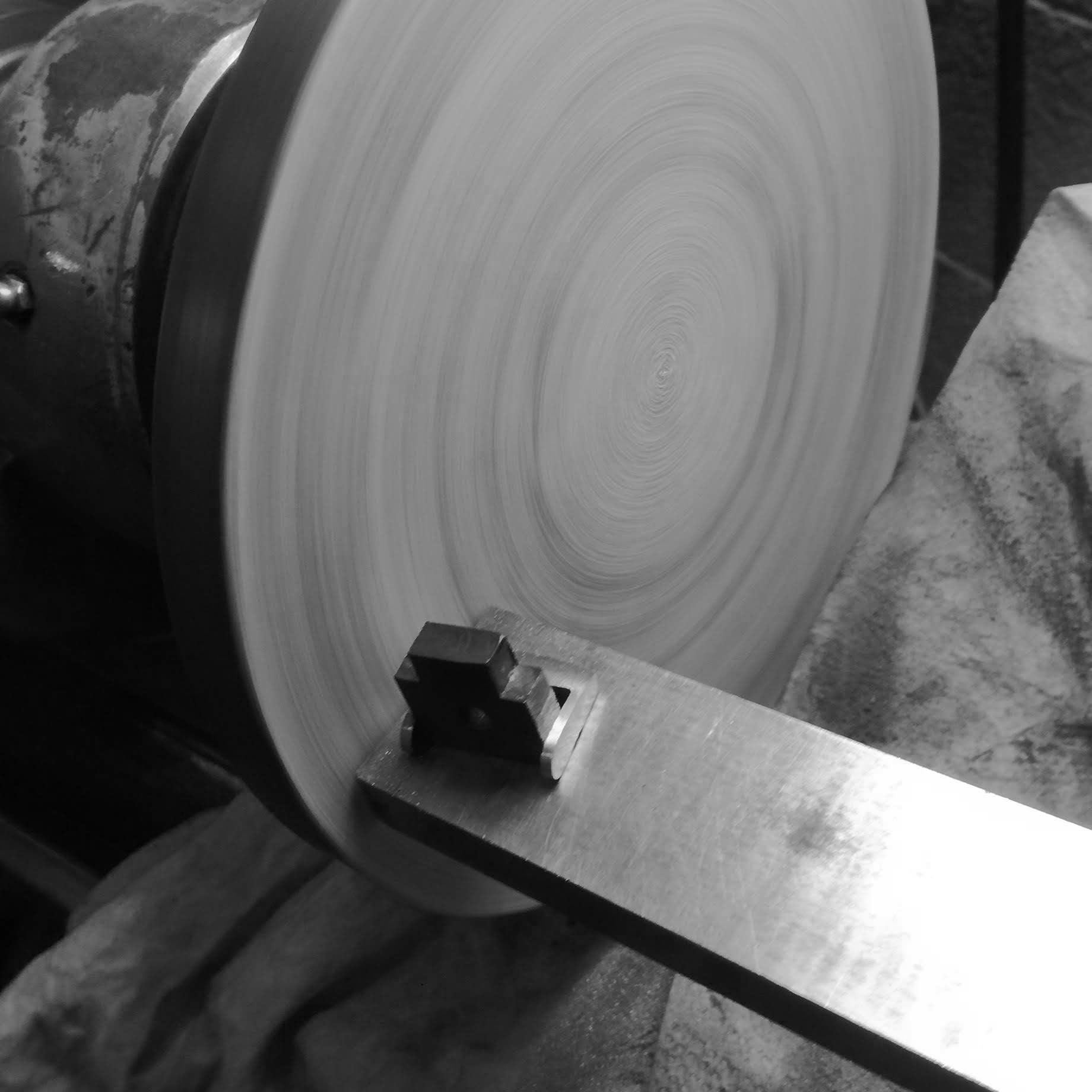
Here I clean up the surface of the dial with a fine grit while on the lathe.
Brushed finish, it is stainless, so it reflects a lot of light.
Since the dial is so thin and the railroad track also thin, it is hard to easily discern with this brushed finish.
Here I start to create the matte finish, using low grit diamond grinding compound on a zinc block.
It becomes matte in finish, however, since stainless is relatively soft, it is difficult to get a deep matte finish, so I do this over various stages and applying different pressure.
Taking a break, and inking the dial again.
After the last grinding, you can see the surface difference from the outside lip of the dial.
Another look at the dial with light on it, showing how the matte surface does not reflect light.
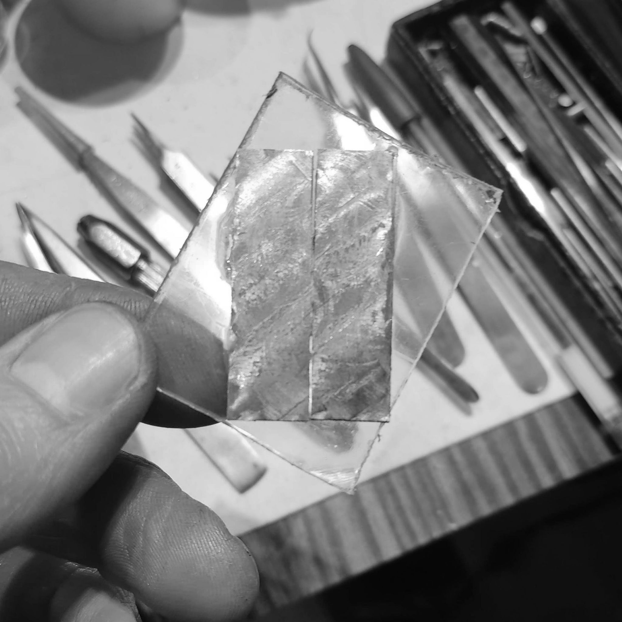
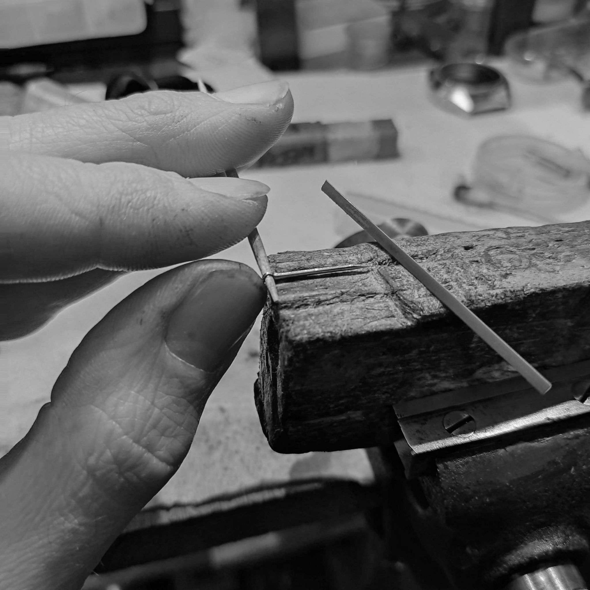
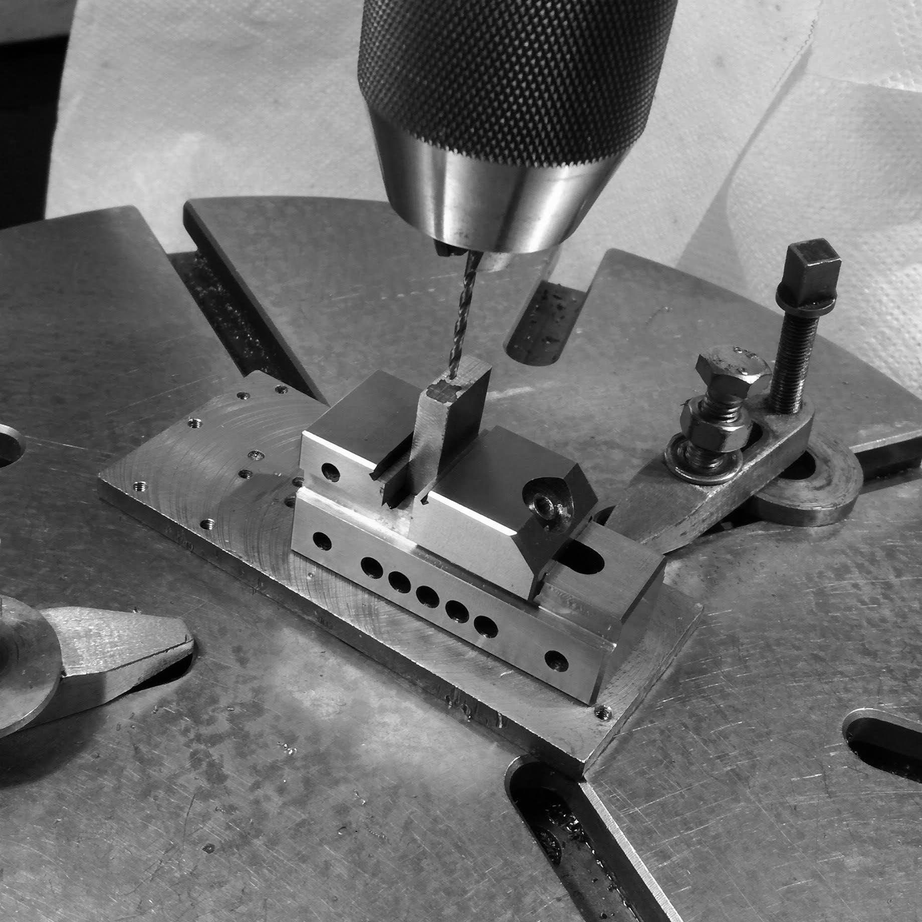
Here I start cutting the spring steel to manufacture the hands. Since the plate is 4mm thick, I split it in two, as the hands will be less than 1mm thick.
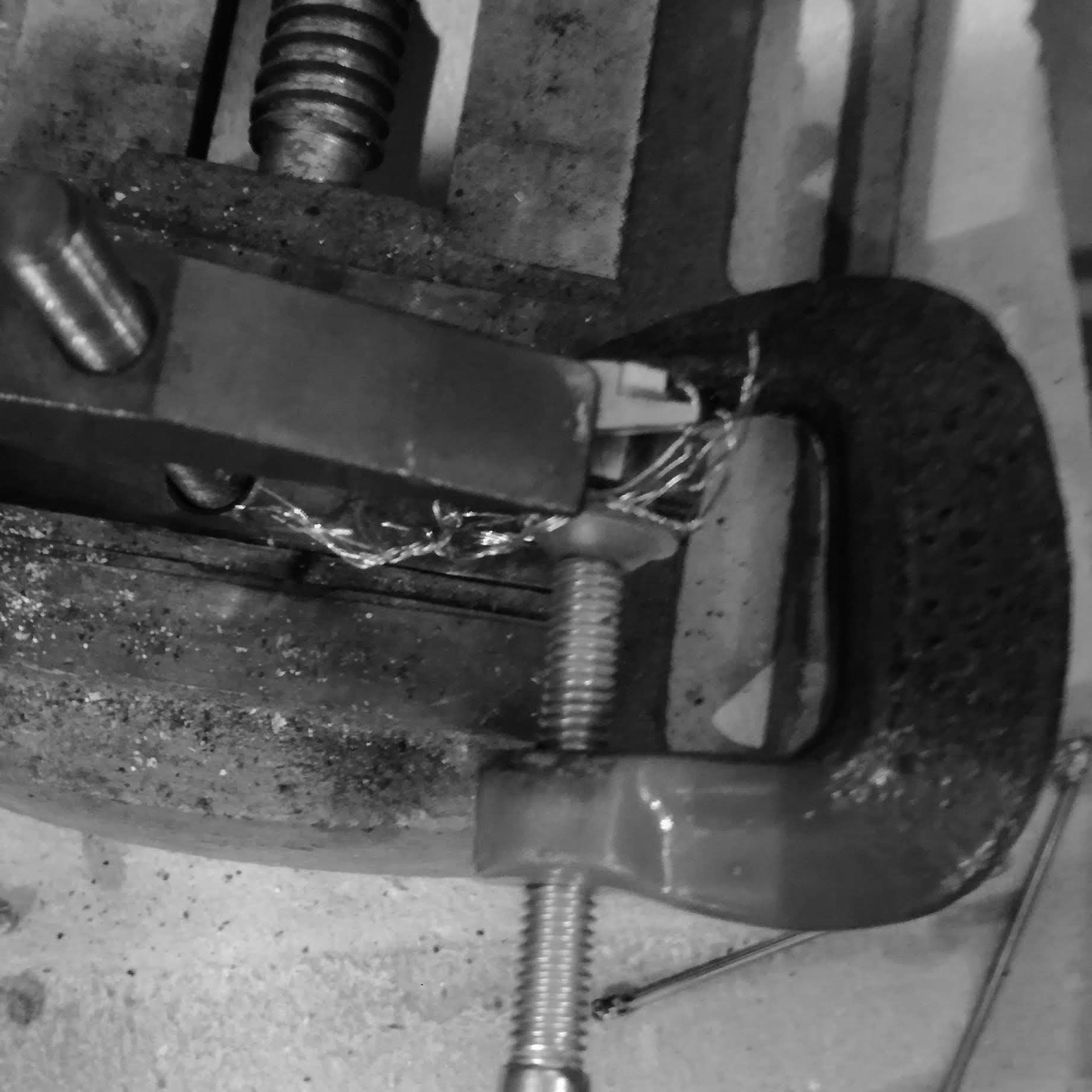
Using a slitting saw for something like this is very time consuming. The saw needs to go at a very slow speed (as it's a steel saw, not tungsten carbide), and has to be lubricated in continuation.
This cut took over 45 minutes of slowly moving the saw through the deep cut. This way, the saw itself is not ruined.
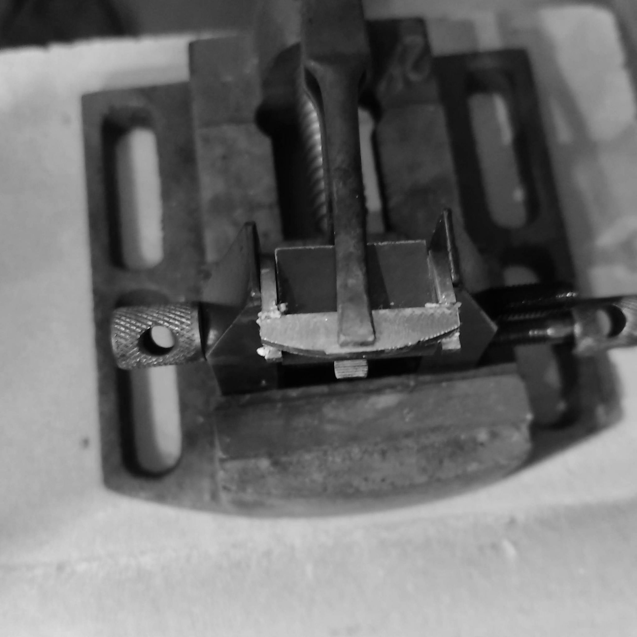
After the slit is done, I take it to the lathe and use a tungsten carbide saw (at very high speed) and cut the parts off.
The two pieces are cut.
However, the finish is very uneven, as the large diameter steel saw wobbles as it cuts and these pieces need to be made flat.
I cemented them onto a piece hardened steel, and used the milling machine to give the a flat uniform surface.
I placed them at an angle, with a bit of overhang, so that once I soak them in acetone (which dissolves the cement), I can fit a blade underneath and pry them out without distorting the pieces.
They are now 1mm thick.
I cemented the pieces on a piece of acrylic. Acrylic and contact cement is widely used in the watch industry for work holding, as it bonds very well with steel, and acetone can then easily dissolve it.
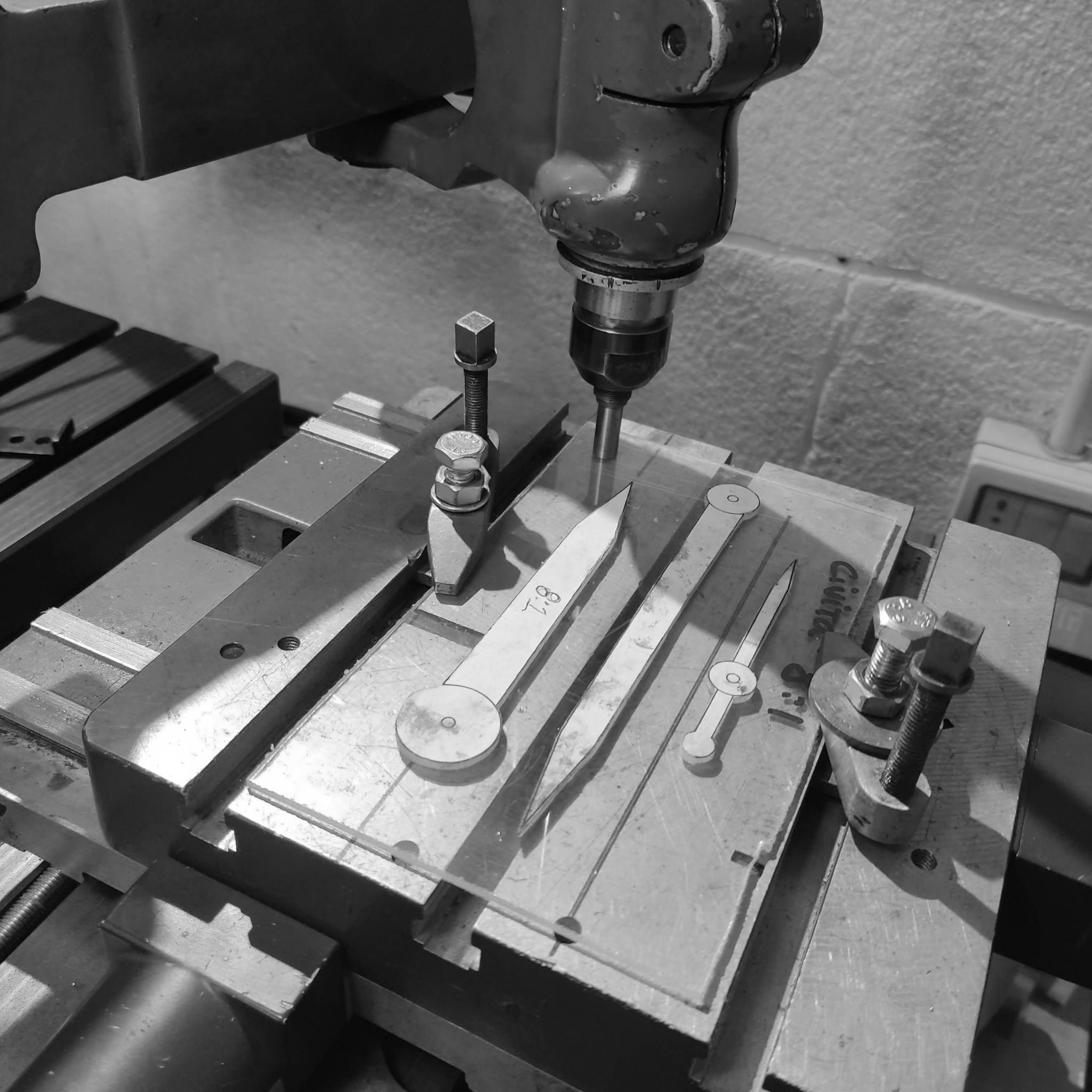
I created an 8:1 ratio scale drawing of the hands, and glued them onto acrylic pieces.
Like with the case, these were then sawed out.
Then they are glued onto another piece of acrylic. The bonds were let to dry thoroughly, as it's important that the patterns they create do not shift - if they do they ruin the part being machined.
Here the pieces are placed on riser blocks so that the piece is close to the spindle, since in a pantograph of this particular design it is not easy to bring the spindle down much like a normal milling machine.
The tracer table, which guides the milling spindle to create the shape of the pattern at the reduced scale.
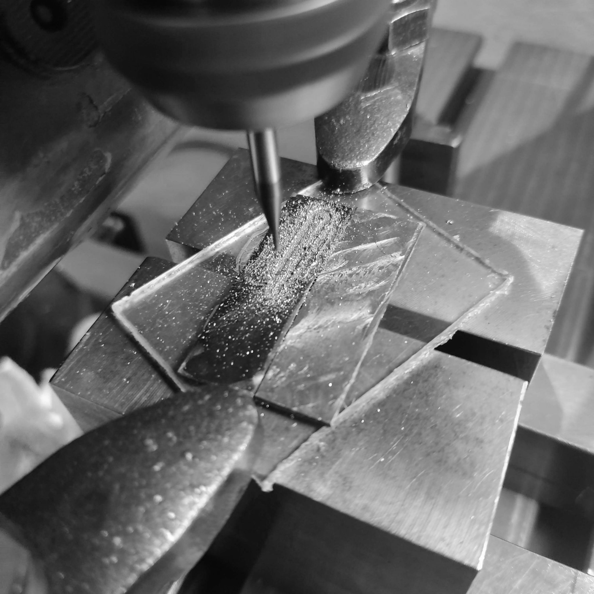
Starting to mill out the pattern. Milling through 1mm of material takes a lot of time, since the cutter diameter is 1mm, and one has to do 0.1mm passes, and moving very slowly.
Almost finished, after each pass the swarf created needs to be cleaned, since it can clog the cutter and cause it to break.
The milling finished. I have made only one set of hands, and have the other plate ready in case.
I then take the plate to the jig borer to open up the holes for the tubes that hold the hands onto the minute and hour wheels.
After drilling, and then I need to separate each hand off. I purposely do not mill through to the acrylic as it risks ruining the hands during the final pass. They can become loose and the cutter can cut into their profile.
I saw the hands from from the frame.
The sides of the hands have to be cleaned up substantially. To do this, I hold the hands against hardened jaws (which will not be effected by the files). This is a very slow process, where I start with a fine file and the use a ruby file
This is an intermediary stage, you can see all the imperfections on the side of the hands. It is important that the sides are cleaned up at this stage, because once the upper profile is given, it is difficult to hold the hands to work them, without ruining the profile.
Hour hand cleaned up.
Using the ruby file to clean up the sides of the minute hand. I also reduced the thickness of both hands slightly, as they were too thick when I saw them on the watch.
A first impression of how the hands look. I painted them blue to give contrast. We will get a better impression once I make the hubs and the hands are lying in the correct plane.
I cut a piece of spring steel to use as stock for the center hubs of the hands.
The piece cut.
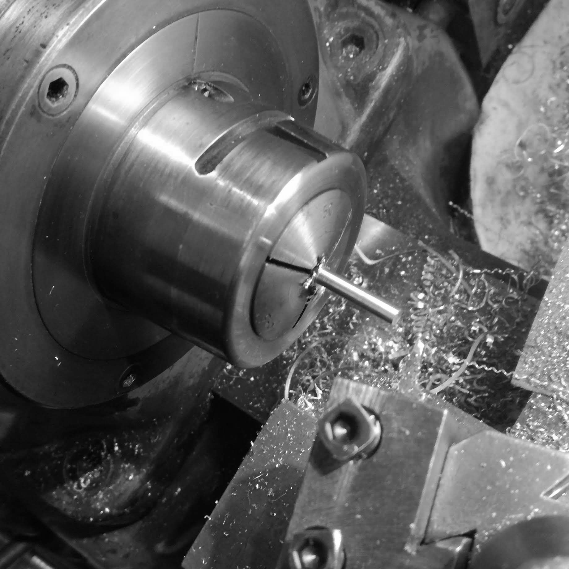
Here I put it in a collet to turn it into a rod.
The rod turned and then it is cut.
Now I start to turn a 3mm brass rod to create the outer bevel on the hands.
I center drill the rod so that it can be supported on the opposite end, and not bend under pressure.
The rod is finished.
I forgot to take a photograph of when I milled the slot on this. It is a slot that is at an angle, so that the hand will be slightly thicker at the hub (center) and thinner at the tips.
Here you can see the profile.
The hand is cemented on, and with a high speed grinding cutter, I slowly give the rough profile.
I started to work on this, and realized something was off with how the bevel was coming out.
As you can see, the tip was not thinner, but thicker. I should have placed the hub on the outer (right hand side) of the rod!
So this was taken off, and recemented.
Here is the correct placement now. with the hub being deeper in the bevel.
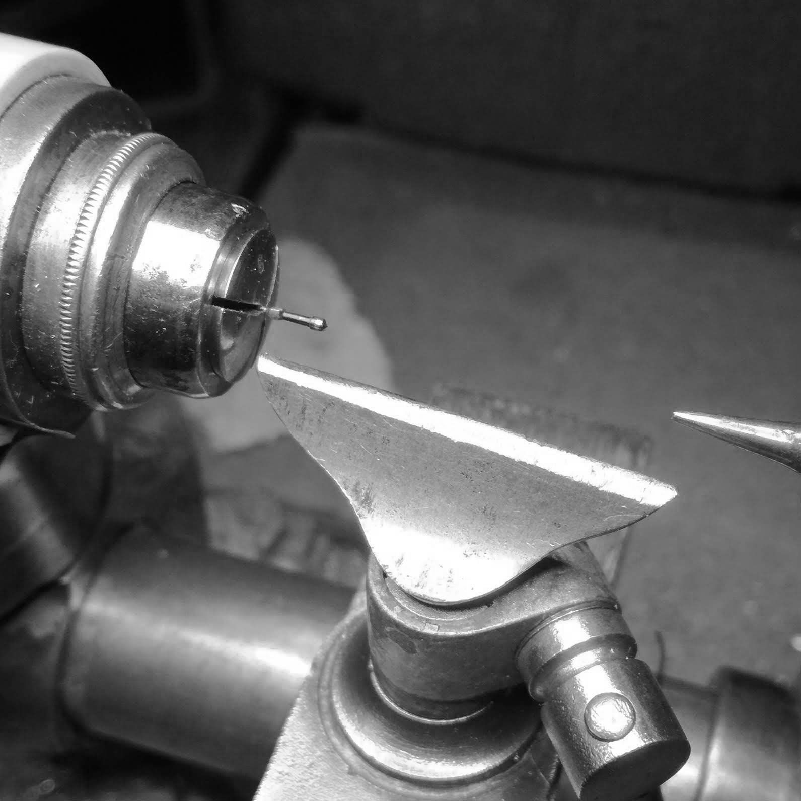
Rough passing the material. Once it is close to the 3mm diameter, I take this to the watchmaker's lathe.
Here I use rollers to support the file, so that I slowly file off material until I arrive at the 3mm diameter.
After starting with a fine steel file and then moving through successive grits of sandpaper (attached to a hardened steel support), the second's hand is ready for hardening.
The same work was done to the hour hand.
The same work was done to the minute hand. From the cutting of the brass support to this stage, a whole day was spent on getting to this stage.
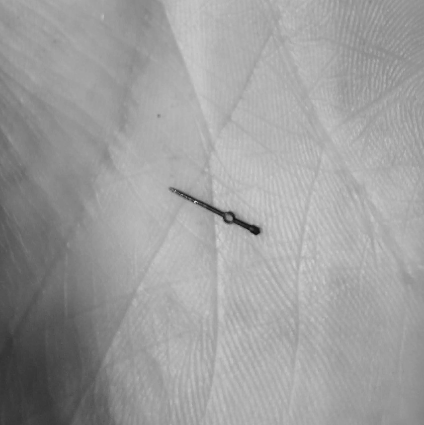
Hands painted blue for a rough impression.
Steel for another impression.
A color picture with steel hand. I need to create the hubs, and then once done, i need to harden and temper the hands before giving them the final polish and bluing. work on the seconds hand will be done next.
Here I touch up the side of the hand to correct the angle at the hub area with a ruby filing stone.
I enlarge the hole of the hand to accept the hub. Here I am centering the hole on the jig borer with the centering microscope.
Here is the stock of spring steel to create the hour hand hub.
Turning the interior recess for the hand's loop to fit into.
Here I place the hub on the milling machine and mill out the recess for the hand.
The recess for the hour hand to fit into.
The hub parted off from the bar stock.
Turning the outside angle on the hub.
Drilling the hub to the hole size that will fit on the watch's hour wheel.
The hub after drilling.
A first glimpse into how the hands will look with their hubs.
Turning a new hour hand hub as the recess I milled was not correct (although the diameter was correct, it was too deep and did not look correct).
Of course, there are always multiple failures, and here the cutter caught and broke the hub.
Another view of the broken hub.
Since the cutter broke, I had to grind the cutter again. I did this various times as the recess for the hand increased in depth.
Profile view. The profile has to decrease in thickness, so that it can fit into the small groove being created to seat the hand's loop.
Here is a first test in the 3rd hub being made.
The fit is good.
The recess is then dressed and cleaned.
Here I start the hub for the minute hand.
The final size is reached with a reamer (here a 5 sided hand reamer), since the minute hand arbor is a non standard size.
Checking the fit with the minute arbor (here it is pressed into the minute hub).
Turning the minute hub around (after parting), and creating the countersink in the middle which will be polished.
A look at the architecture of the hand hubs.
Another view of the hub bevels.
The individual portions of each hand and hub are hardened.
They are hardened as previously seen, in charcoal powder so that the charcoal prevents air from ruining the surface of the hands.
After reaching bright red temperature, they are quenched in oil.
A magnet is used to fish the hands and parts out.
After cleaning they are polished in order to see the color change when tempering (this step is not shown here).
After tempering, each hand and corresponding hub is silver soldiered together. I had to use a series of metal pieces to make sure the hand is correctly positioned and not out of level with the axis of the hub hole.
After soldering.
Both hands are then boiled in a citric acid solution (jeweller's pickling solution) to remove the flux that is cooked on the hands.
Initial view of the hands. Since the soldering process creates intense heat, there are areas where rust occurred and this has to be cleaned off.
The hub is initially cleaned.
Cleaning up the solder from the bottom of the hands.
Initial light sanding to remove the rust on the hands.
Polishing the minute hand hub.
Here, I use a piece of wood with diamond paste to polish the interior center hub.
A first glimpse at how the hands look on the watch.
Now I start on the second's hand.
However, after an hour of work on cleaning up the sides, I realize that manufacturing it like this will create many problems during the finishing stages. And I abandon this process, and start anew.
I use a rectangular piece of spring steel, and turn it into a shaft.
I create a central portion for the hub, while turning in centers. This is because it is extremely maleable in this annealed state, and being thin, it can very easily break.
I cement the hand on a piece of plexi glass.
And drill the hole for the second's hub on the jig borer (here I am centering the hole).
Drilling the hole.
Then, I use a jig to hold the hand perpendicular to its axis, so that I can clean up the area around the hub.
Slowly arriving at a circular shape on the outside of the hole.
In order to machine the hand further, I need to harden and temper it.
After hardening.
Initial quick polish to get a surface finish bright enough to see the color for correct tempering.
Tempering with a slow flame.
Tempered to purple blue hue.
Turning the back pip of the minute hand. I decided to go for a conical end instead of a circle (since this has become trivial by its repeated use recently).
Turning the hub for the second's hand (here I am drilling with a 0.2mm drill).
The rough second's hand hub.
Turning the bevel on the top side.
Starting a new hub, since the first one's hole was slightly out of center.
This one is centered correctly.
Initial polishing (using a zinc bar, with diamantine powder).
Turned a small brass hub to use as a support for the second's hand while I machine it partially flat).
Here I use the brass hub so that the hand sits horizontally on the wax chuck (I cemented it).
Here using an overly elaborate setup, for a simple operation.
I needed to grind the bottom of the hand flat, and grinding affords the least torque on the piece (to prevent it from flying off or from bending).
The bottom of the hand flattened (since the rear pip was thicker than the tip of the hand, and creates problems when setting the height of the hand on the hub).
Here I blue the hands for the color photographs I shared with you.
Bluing the hands allows me to better gauge any defects on the hands, and here I am reworking both hands to remove small irregularities.
Finishing further.
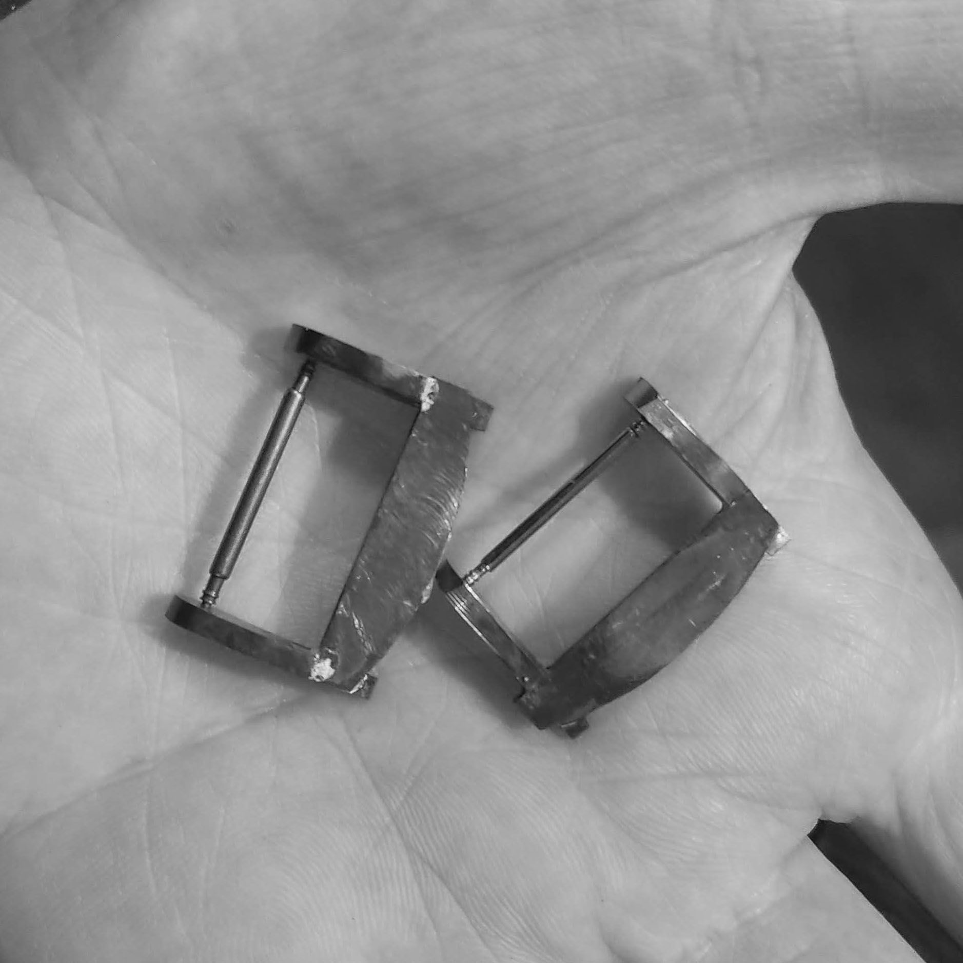
Here I start the two buckles. I need to make two, since the rubber strap will take a 22mm buckle, and the leather, a 20mm buckle.
I use raw stock pieces from the same billet rod used for the case. They were hand sawed, so here I turn them into usable pieces by flattening them.
Milling the first part flat.
milling the second part flat.
Here I mill a slot for the traverse bar of the buckle frame to sit on.
This part here will be the the two pair of sides of the buckle frame.
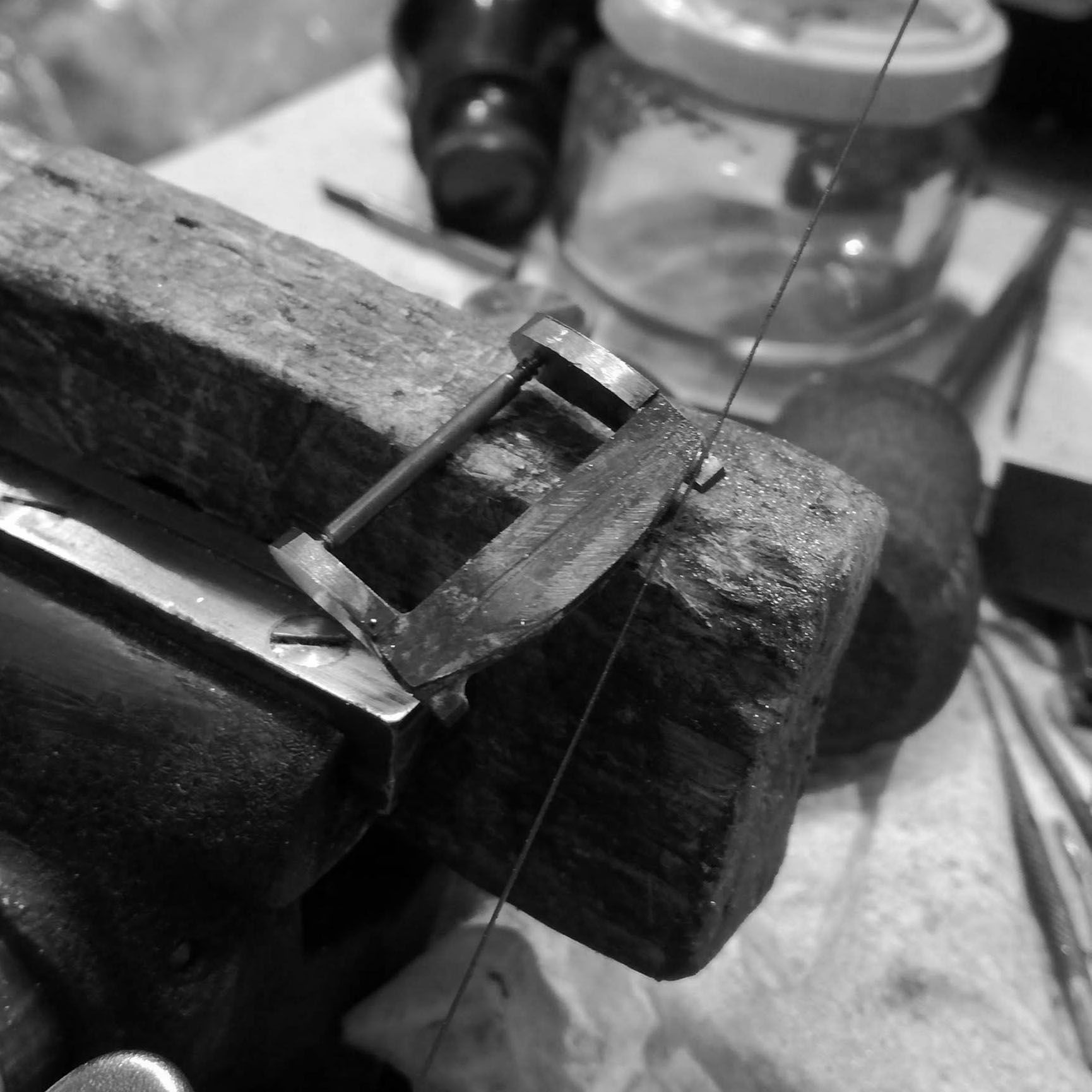
I slit the four parts
And then finished cutting them with a hand saw as it is a difficult part to hold, and cut mechanically.
Here I slit the top of the traverse bar of the buckle frame.
As in the previous parts, finishing the cut with the hand saw.
Cleaning up the lip that is left over with a rough hand file.
Then the part is put on the jig borer and run at the highest speed with the diamond grinding cup, to act as a surface grinder.
I slowly work both surfaces so that they are parallel to each other and uniform in texture.
Grinding the sides of the buckle frame.
This operation, done without coolant liquid, leaves a very dangerous blanket of steel and diamond compound powder that needs to be meticulously cleaned. As if it finds its way in the cross table ways, or spindle, it very quickly ruins the machine.
Image of the parts ground flat for further working.
Here I am cutting a piece of low quality steel to make a holding jig for soldering the parts of the frame.
In trying to make the operation quicker, of course, one ruins a cutter. Since this steel gums up and tends to catch the blade. So a 20 euro second hand blade gone to waste.
Using a slower means but more secure, with the milling machine.
Machined to 22mm for the rubber strap.
Here I clean up the surface of the cross portion of the buckle frame.
Before. Machining, unless at very high speeds like modern machines, tends to leave an irregular surface (here augmented as I didn't worry about the correct feed and depth of cut), and warrants a second finishing operation.
After.
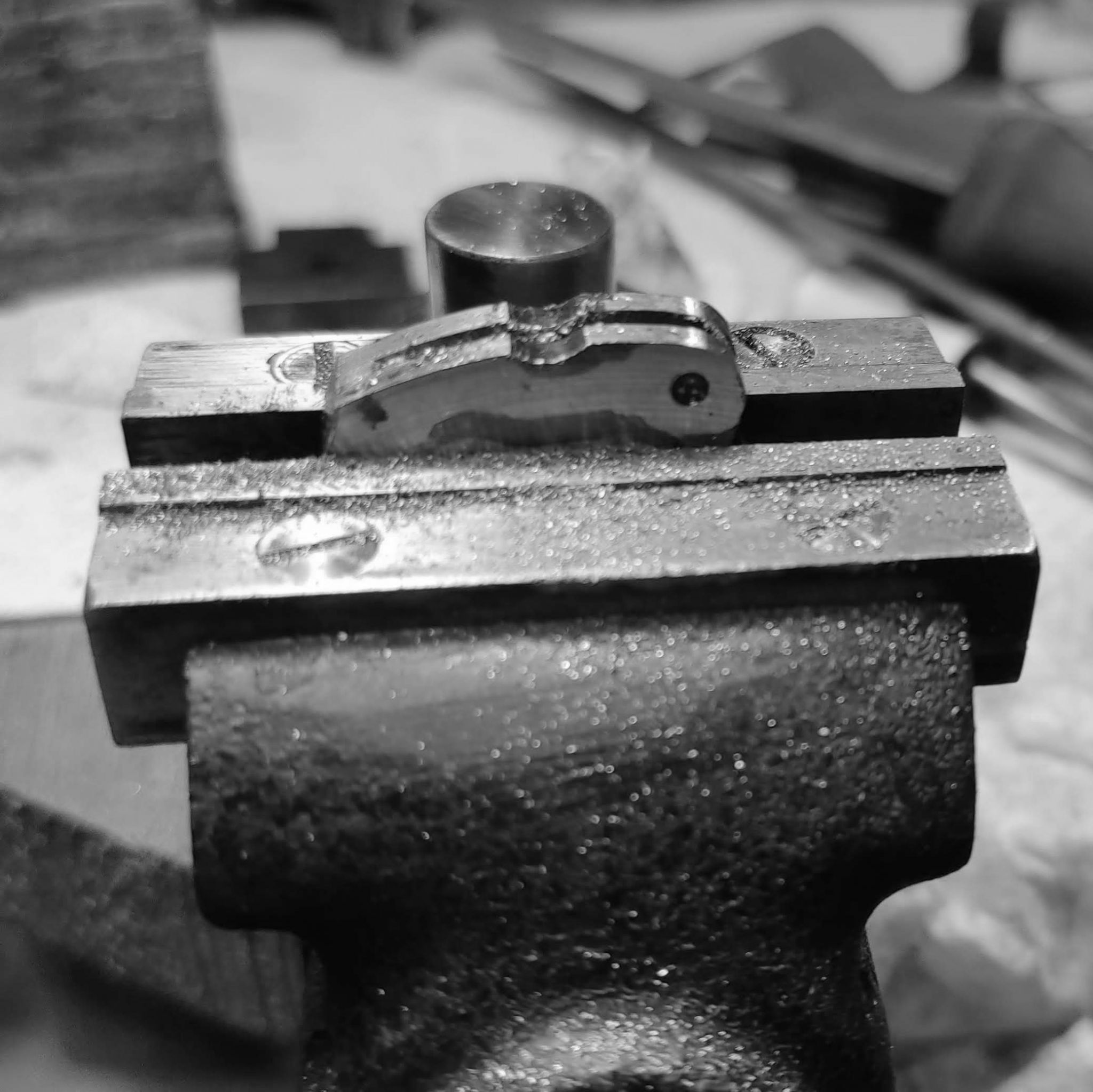
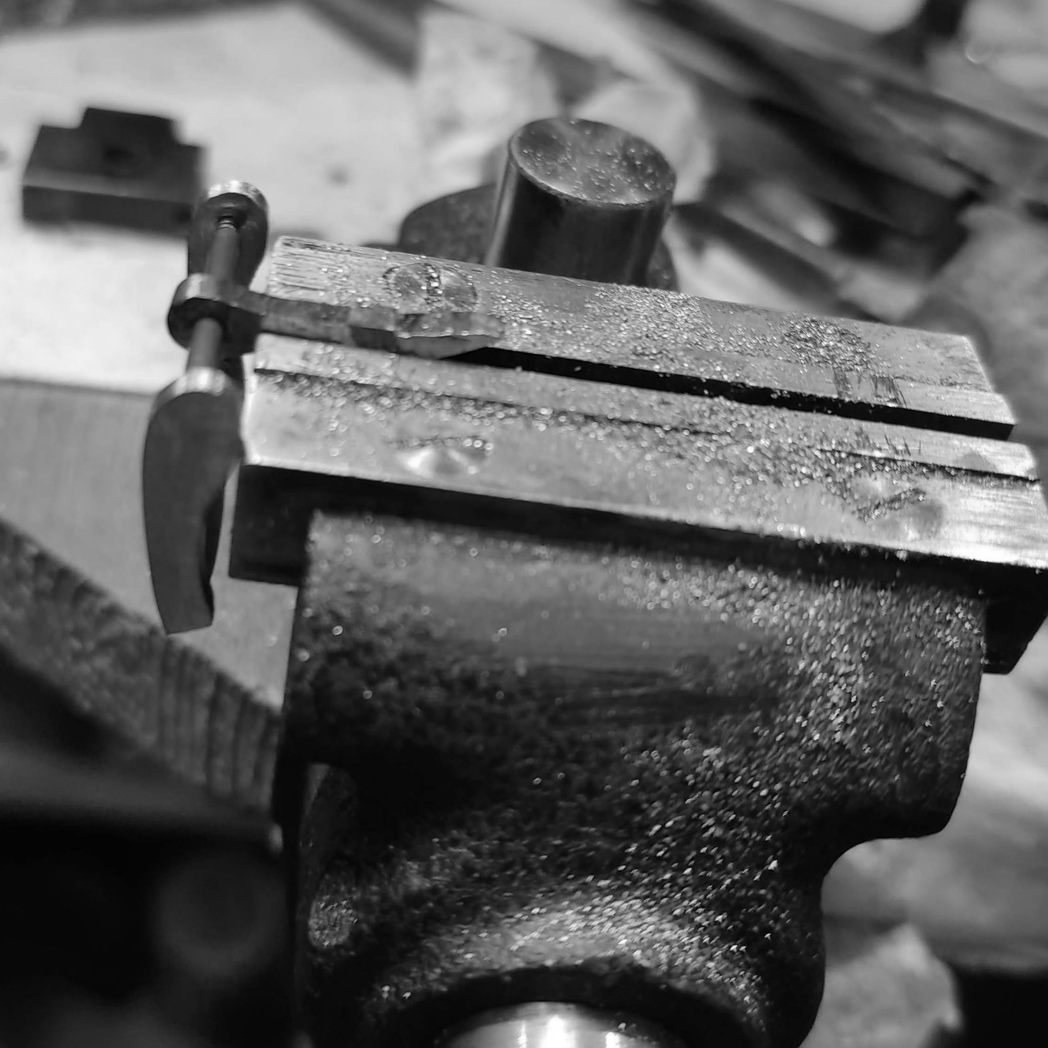
Both sides are placed in a vise and a rough cleaning and shaping is done to them before soldering.
Cleaning up the top of the buckle sides.
Further rough shaping the parts of the buckle before soldering.
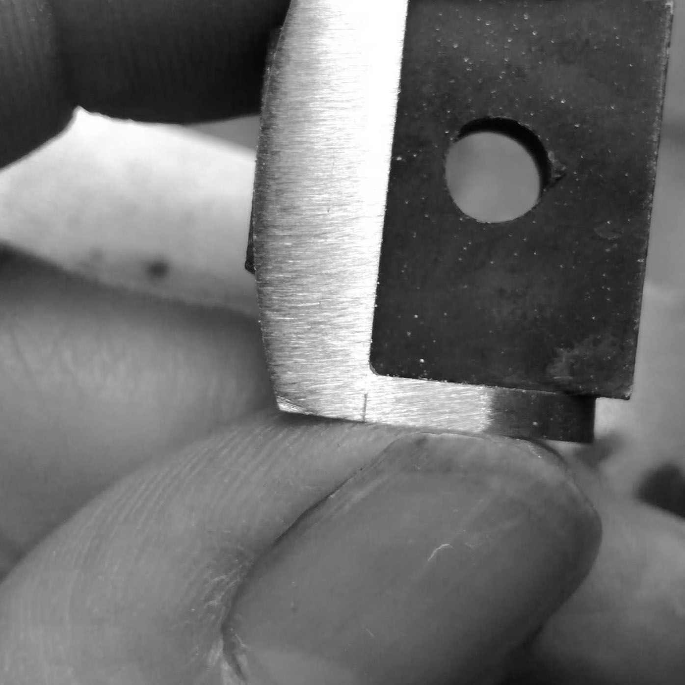
Marking out the area for the springbar.
Drilling the spring bar holes.
Preparing the buckle frame for soldering.
Placing the cross bar of the frame.
A failed first attempt at soldering the frame. It failed as the 22mm steel slug absorbed too much heat, and didn't allow the solder to flow properly.
This resulted in oxidation forming throughout the parts.
After sanding all the parts anew, and soldering, here is a successful solder, where it flows into the entire crevice between the two parts.
Preparing to drill a hole in another 20mm wide steel slug, to act as a jig for soldering the 20mm leather strap buckle.
Soldering the buckle in two operations, once on the outside.
And then on the interior - here using simply an overabundant, and unnecessary amount of solder.
Both buckles soldered. Top of buckle view.
Bottom of buckle view.
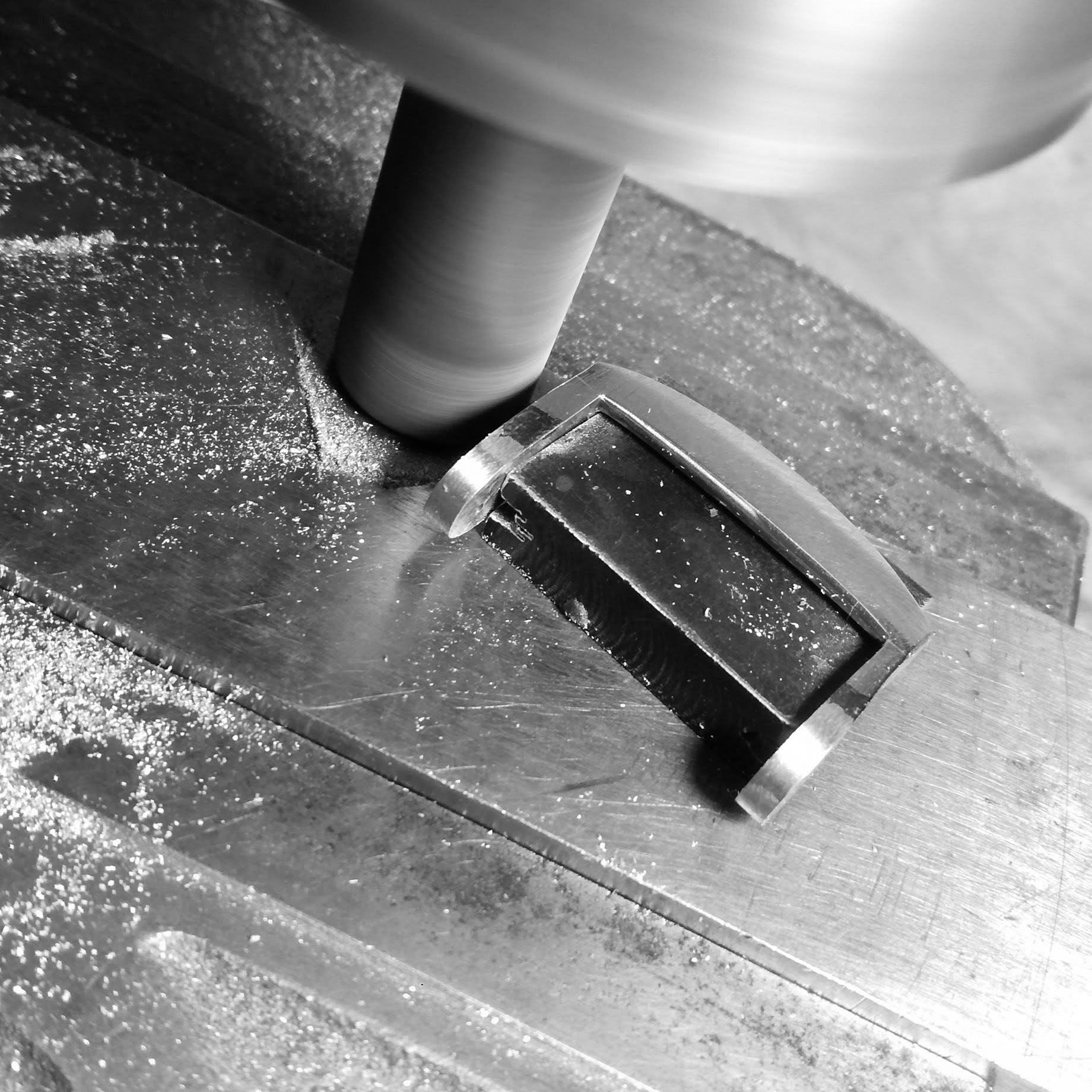
Again onto grinding the outside of the buckle parallel to each other.
Using the sanding disk on the lathe to clean up the front of the buckle area.
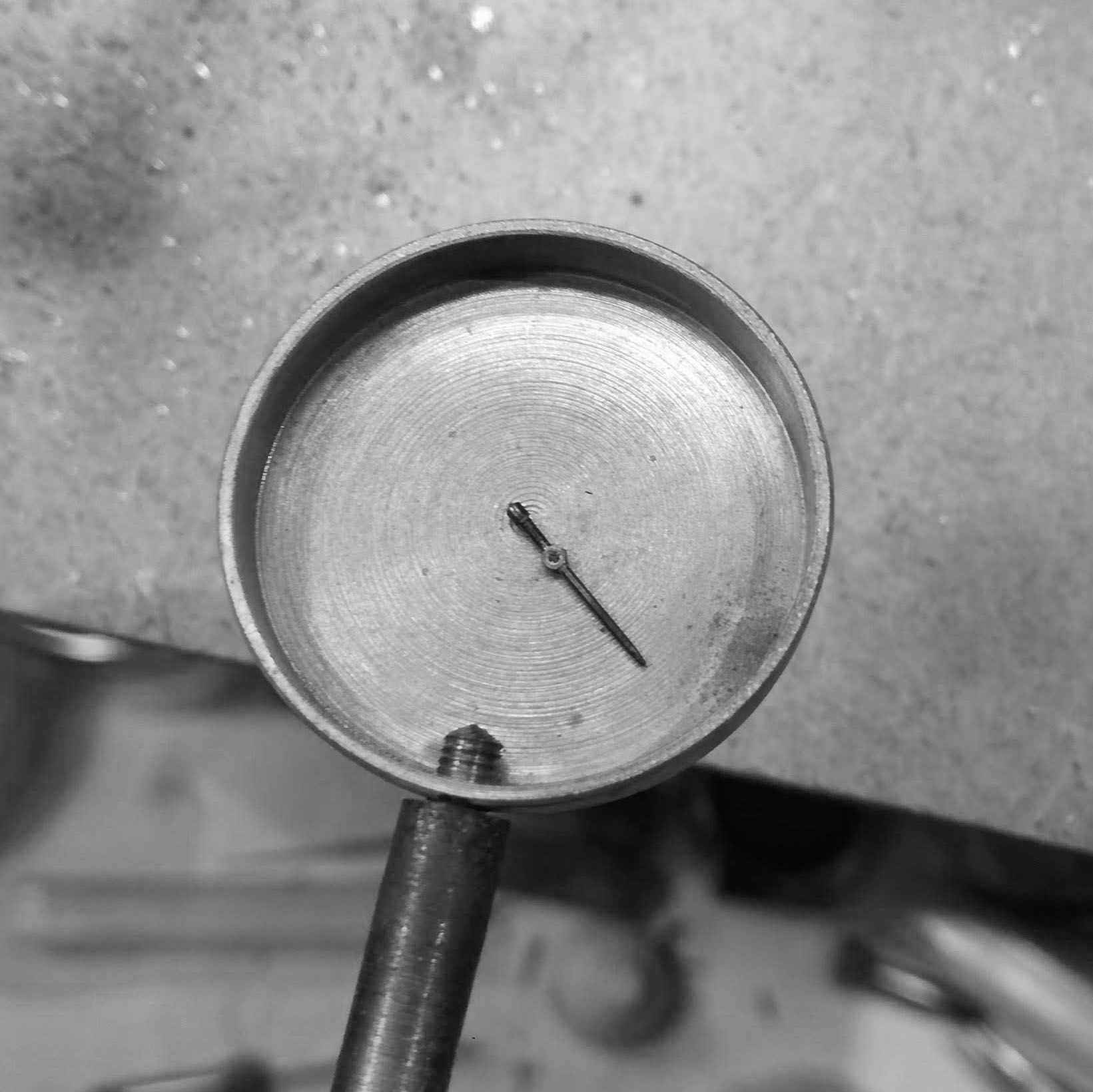
Checking on the dial comparator the height of both sides of the buckle so that it is not distorted on the strap.
Further cleaning of the top of the buckle (sanding away the extra solder).
Using a very rough round file to start forming the bottom profile of the lugs.
Here I am giving the bottom traverse area of the buckle a rounded shape, at an angle, so that the strap sits deeper into the buckle frame.
Finishing the bottom of the buckle with brushed finish, using a piece of wood and sandpaper.
Polishing the bottom of the buckle.
Rough top of the buckle, successive grades of sandpaper are used to remove extraneous scratches.
I use a large round file on the jig borer to cutout the sides of the buckle so there is a taper.
Further work. I have to do this carefully as it is very easy for the part to catch, and be sent flying onto the floor, and thereby denting and potentially ruining the geometry of the part.
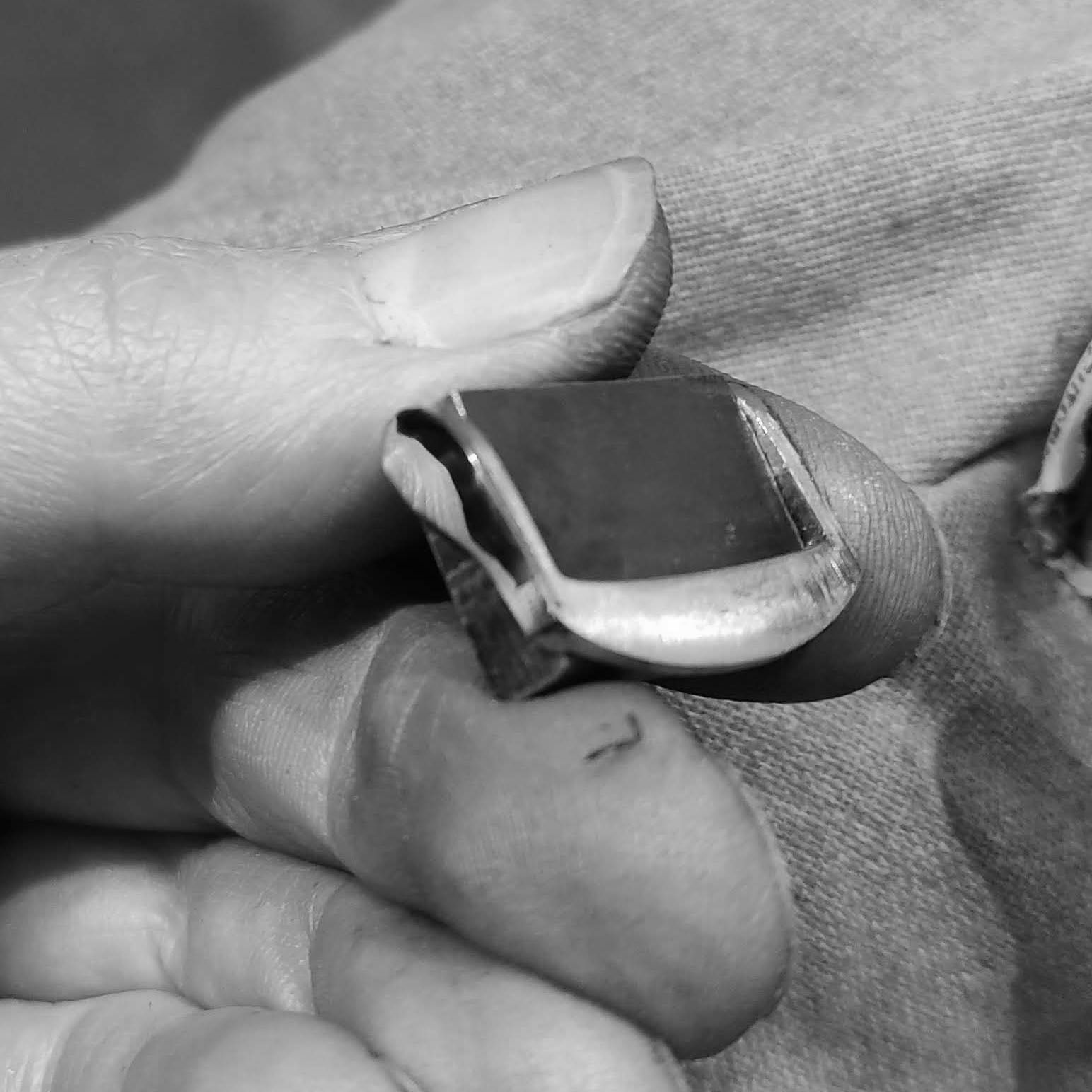
The sides before a lot of sanding and then polishing.
The polished sides. With the top being brushed (it is a inverse of the case) and won't show as much wear with use, if the top was polished.
A very slight flare is seen next to the buckle crossing on both outer sides.
Another view of the buckle with finer polish and finishing.
Still some work to do.
I will leave it like this, I will probably not mill a small recess into the center for the prong to rest in, but I will decide after testing with the strap. As I like how this buckle looks without the recess.
A comparison with the 20mm buckle, before it is finished.
Cutting the excess stainless parts of of the frame.
The top parts cut.
Cleaning up the surface of the top of the buckle.
Still rough, but general shape is being given.
When doing these operations, I noticed that the solder did not run through all the way, and revealed a gap.
This turned out to be a long excursus, since the reason why it didn't solder properly was due to oxidation forming.
After boiling the part in citric acid solution, filing, cleaning and inspecting, I was able to add a large portion of solder which finally filled the small cavity previously created.
Further cleaning on the sanding disc. I had to remove a lot of material from one side, so decided to use this method.
The sides of the lugs made to similar thicknesses.
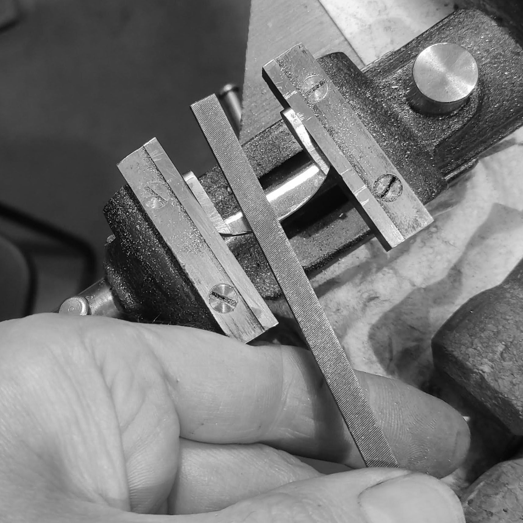
Using a series of files to clean up the bottom of the buckle and give it it's scalloped profile.
Arriving at the bottom profile.
Cleaning up the top of the buckle, so that there is a curve reaching out to the tip of the buckle.
Now starting with the leather strap buckle, which is a 20mm strap-end buckle. The finishing process was exactly the same, so I leave out repetitive pictures here.
Now I start with the prong for both buckles. I use a piece of stainless from the same billet as the case.
The hole for the spring bar is drilled.
Then, the small billet is cut in half.
Cut in half, and finished with the saw later.
Rough contours are given to the top and bottom.
Using blue ink to give a very rough outline. Each prong is cut to measure for each buckle.
Splitting the prongs apart by finishing the cutting.
Using the disc sander (faceplate on lathe with sandpaper glued on) to give a rough shape to the end of the prong.
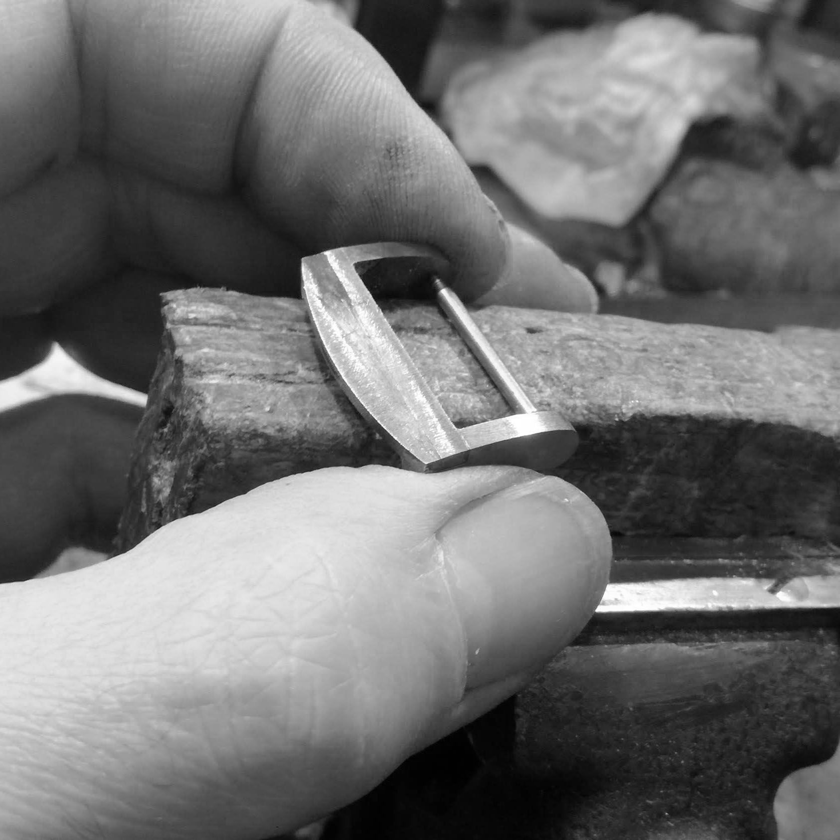
Checking fit on the buckle frame.
Further hand filing of the bottom part to sit properly on the buckle frame.
Grinding both prongs to the same thickness.
Next I file a recess in the buckle for the prong. One buckle, for the leather strap, has a recess, while the one for the rubber strap will not. This is a purposeful choice.
Testing how the prong sits on the buckle frame.
Working on the outer portion of the prong end area.
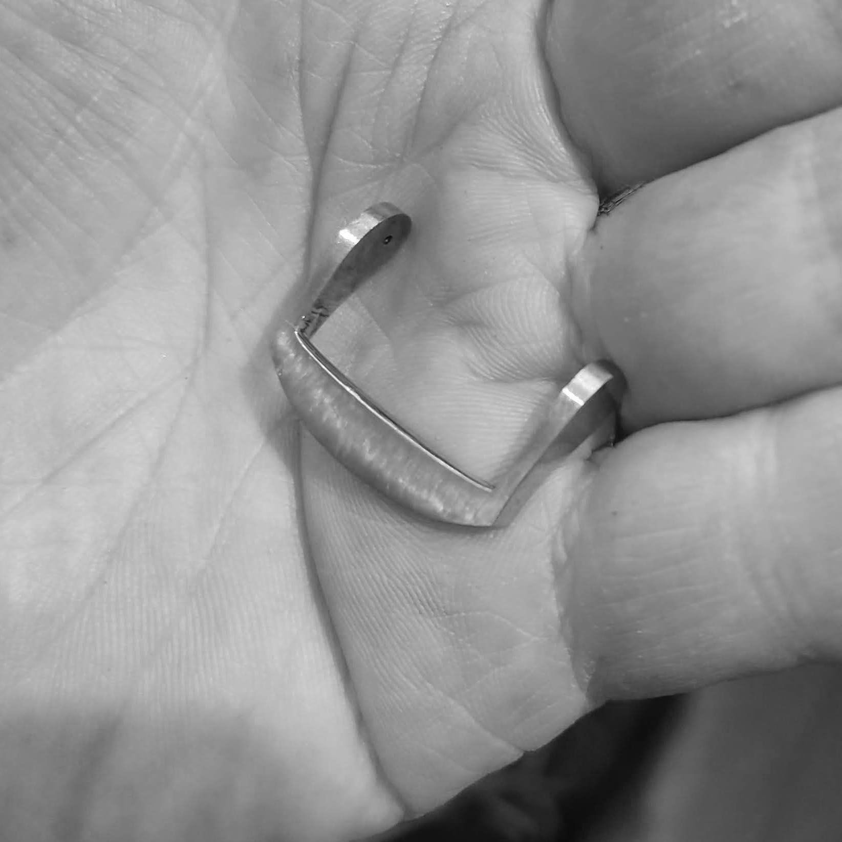
Both buckles finally finished (a brown leather strap is used to test the fit of the buckle, final strap will be black of course).
Another view at the profiles.