The start of the project, with pieces of 316L from the same billet.
First, I start on the center of the case, the part with the lugs.
The billet is faced off so that each side is perpendicular to each other.
I bore a hole through so that I can then hold the billet in a custom expanding chuck to machine the other side.
I machine the back of the lugs.
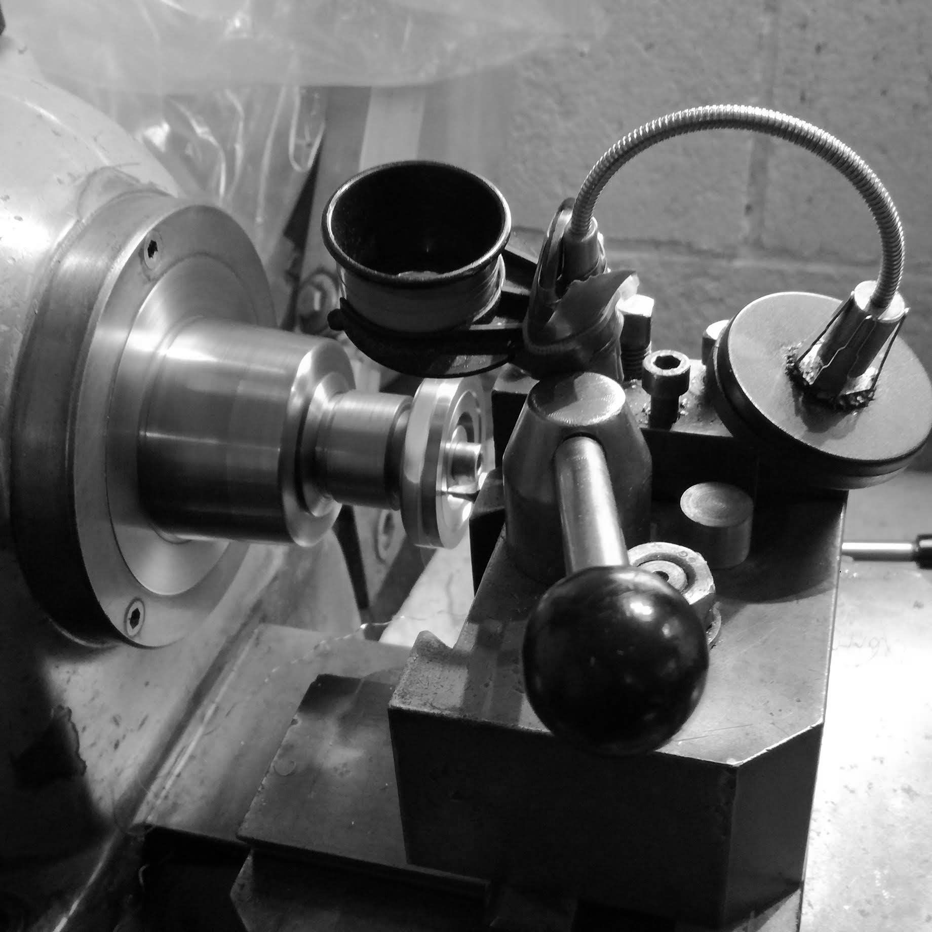
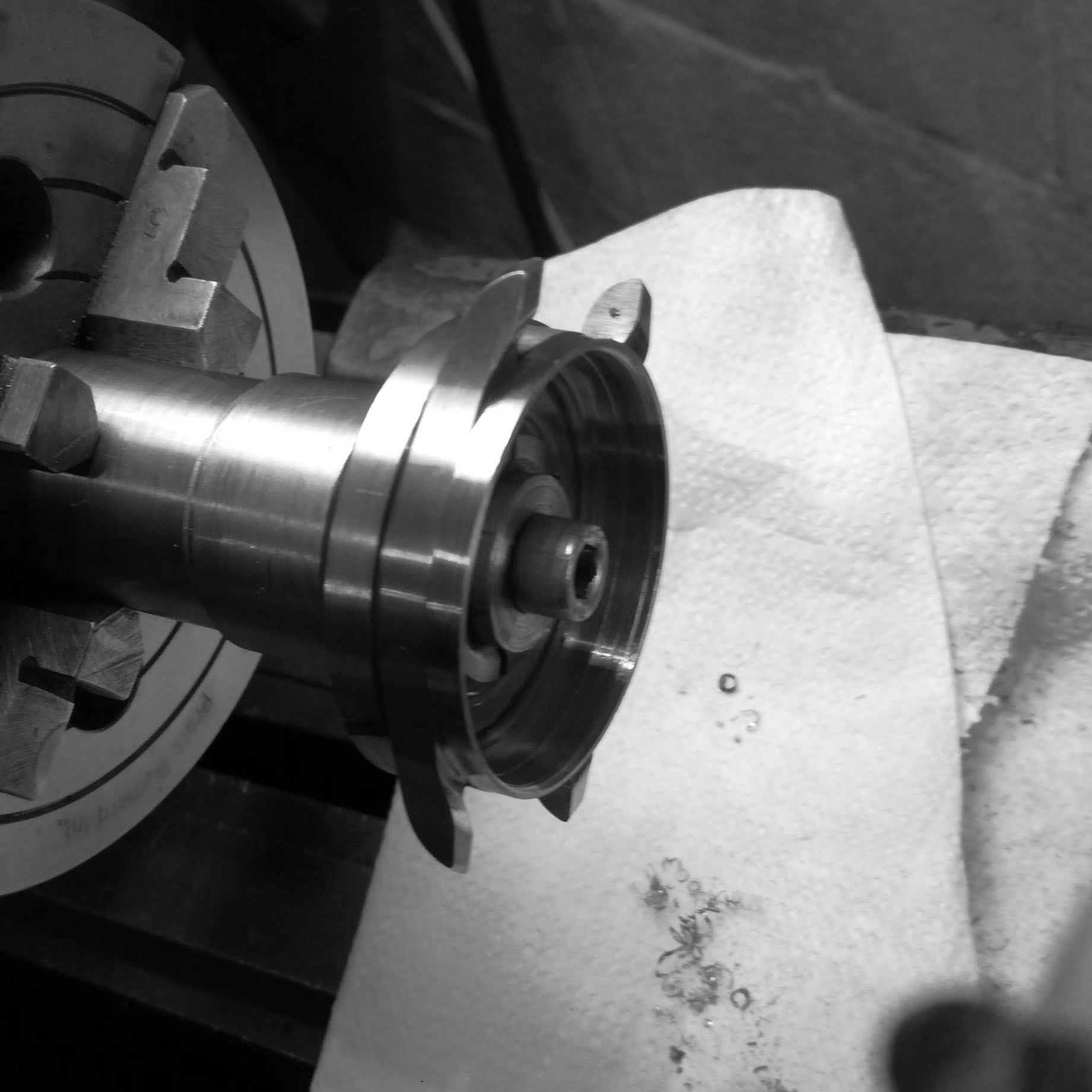
The billet is placed on an expanding chuck, and the profile of the front of the lugs is done.
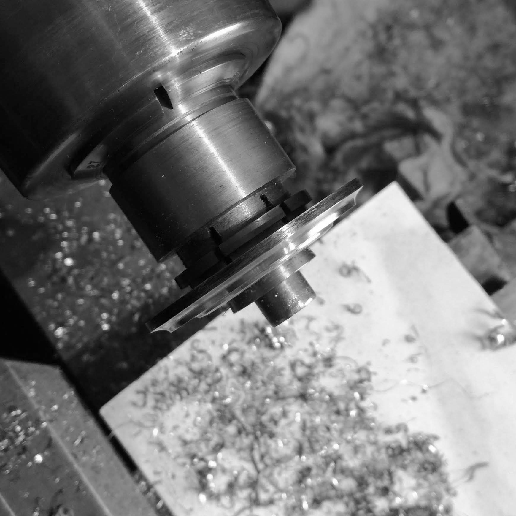
The billet is brought to the outer diameter of the lugs.
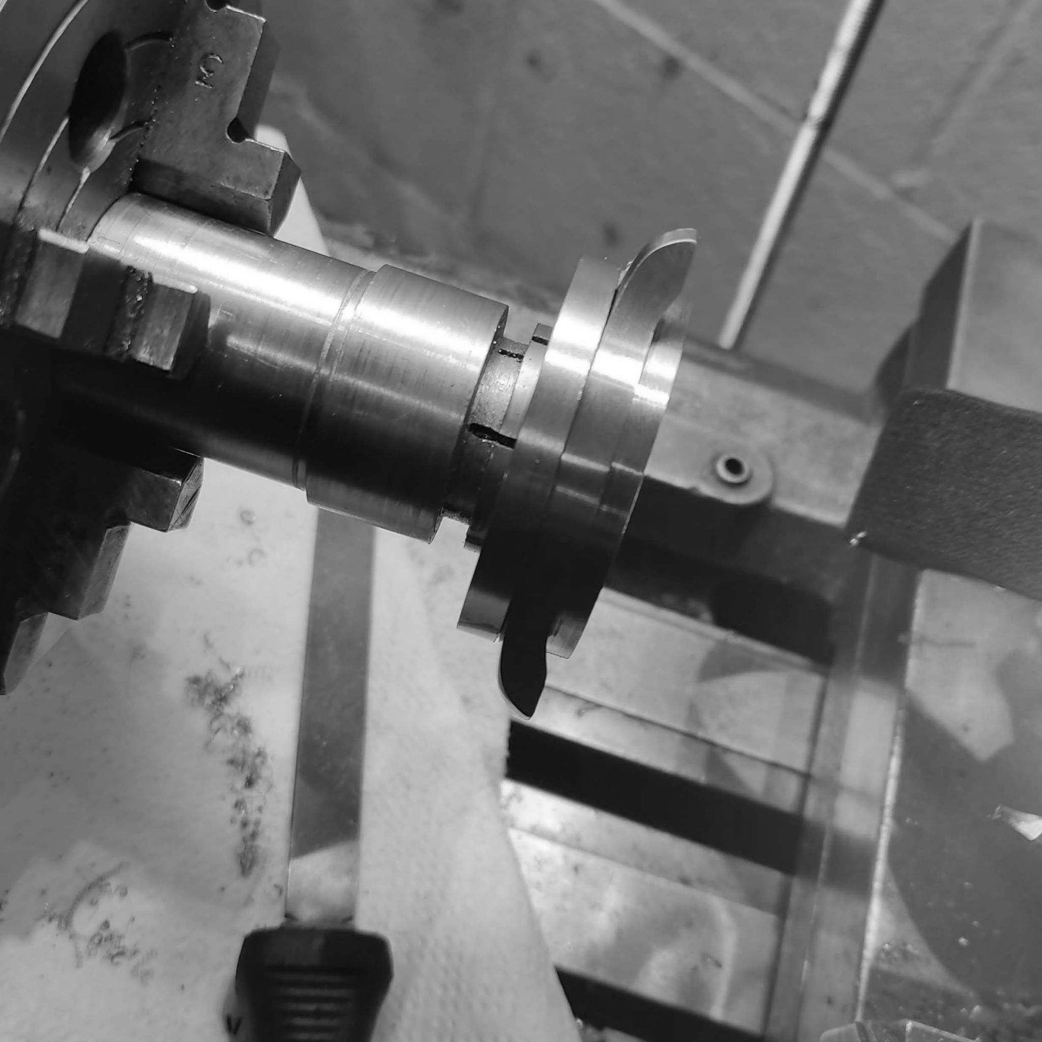
bezel thread diameter is cut and then the curvature of the case is started.
Profile of the lugs.
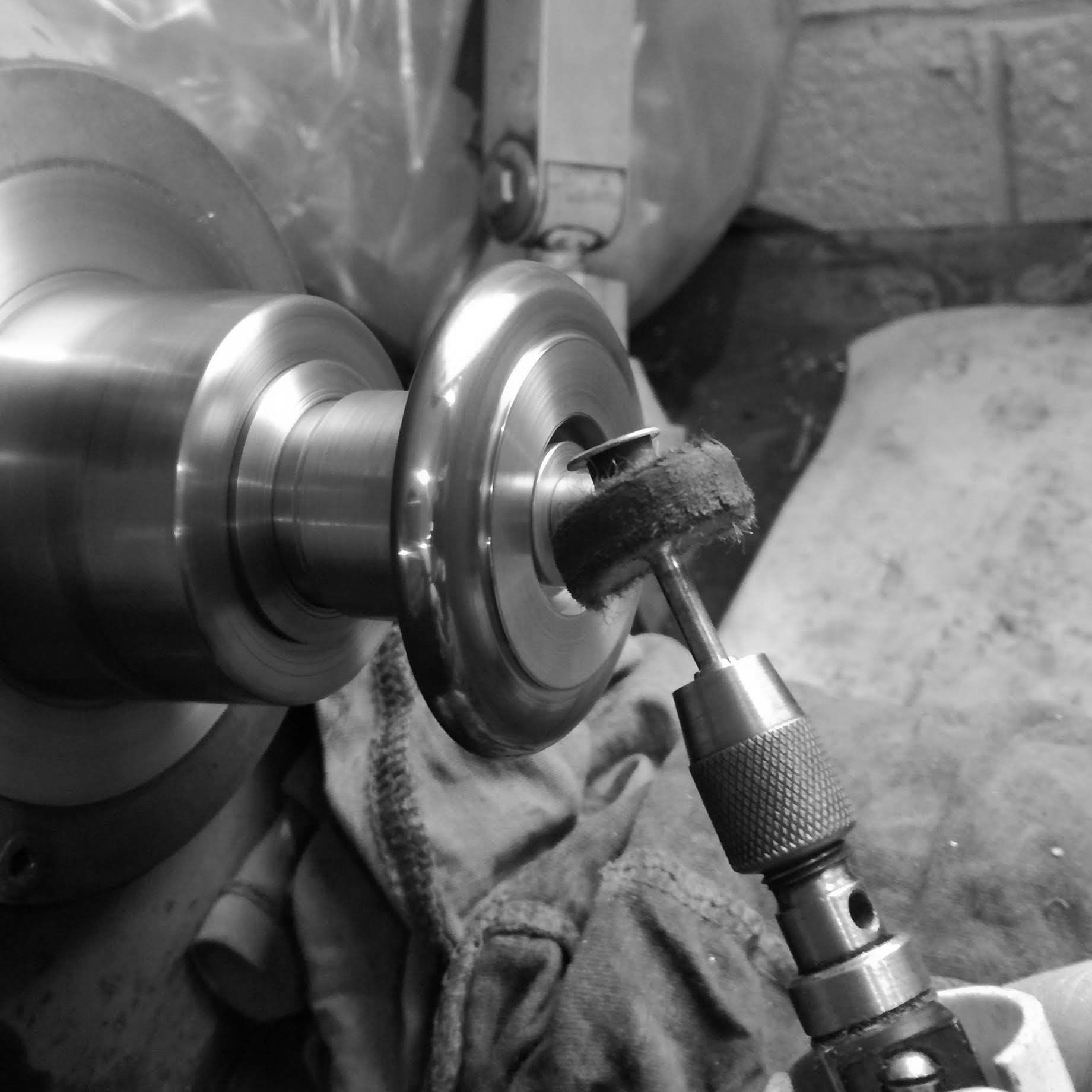
Initial polishing, takes much longer than one might expect, one starts with sandpaper up to buffing wheel.
While this is good, once the watch is completed, a final buffing will be needed to be done.
Working on initial polishing of back of lug area (using a tungsten graver to clear away machining marks).
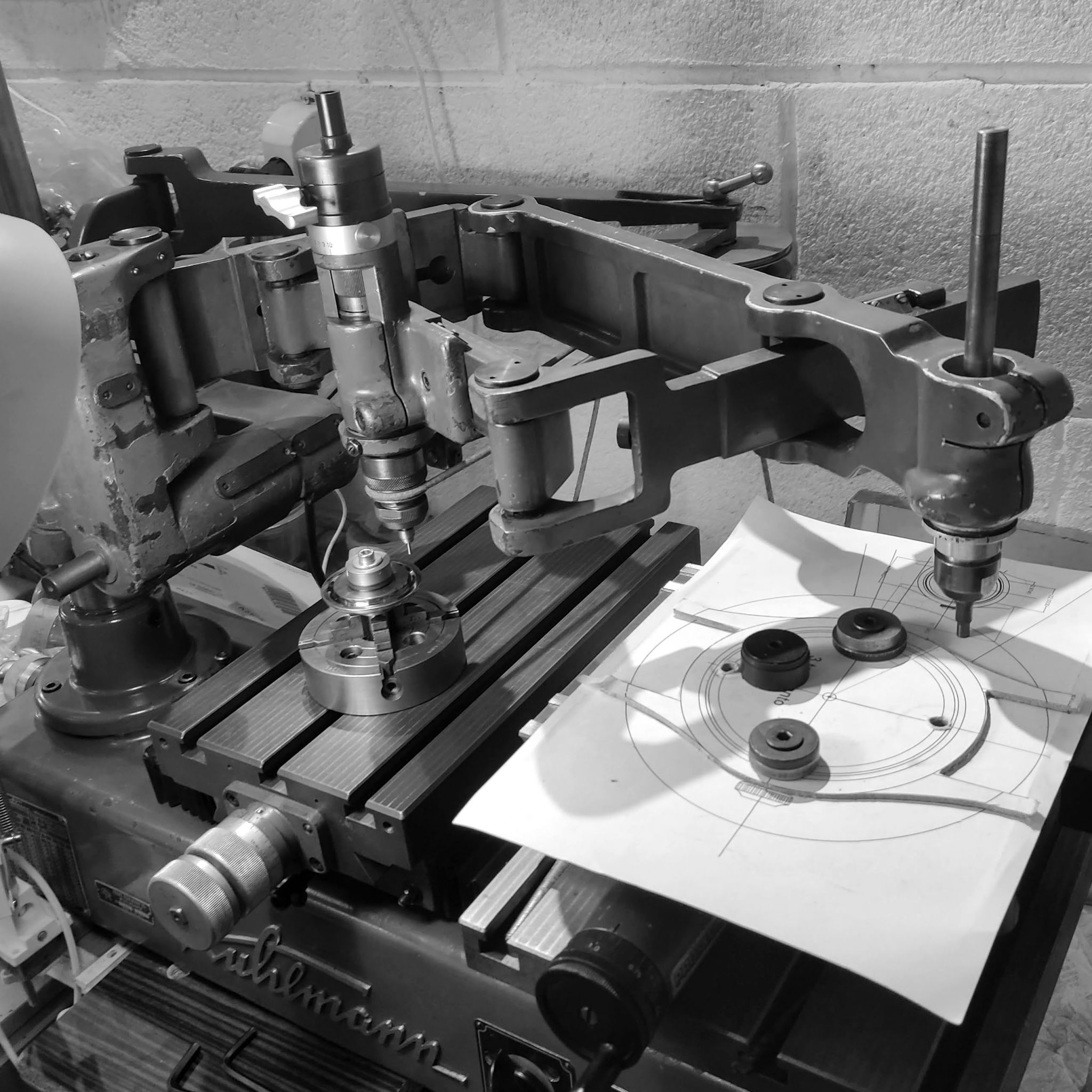
Using a pantograph to machine the lug contours. A template at 3 to 1 is used.
This is glued to hard particleboard, cut out as it will be the guide for the pantograph tracing arm.
Using a Kuhlmann 3D pantograph to mill out the side profile of the lugs.
This is a very time consuming procedure lasting over 6 hours of slow milling, each pass takes roughly 0.2mm off of steel.
I leave the dimensions slightly larger to finish it by hand, in order to get the best quality.
Roughing out the milling marks with a cylindrical file held in the milling machine.
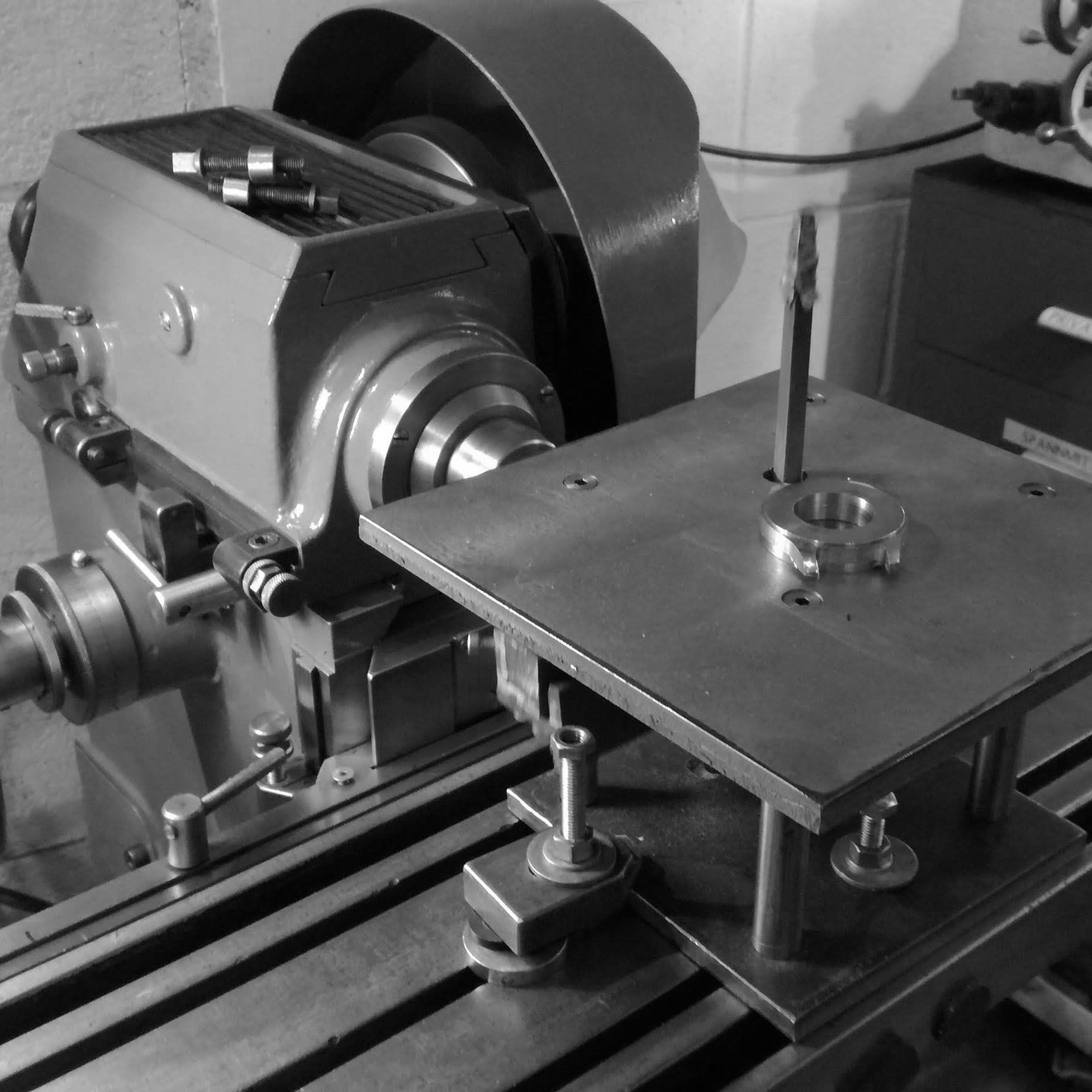
Using a shop-made die-filing machine on the Aciera F3 milling machine to file the interior portion of the lugs.
This is very slow work, as the file allows very precise results, but slow going.
Right interior lug is near completion, compare with left interior round angle, which represents the diameter of the milling cutter used on the pantograph.
After more than 5 hours of continuous work, all four interior corners are near completion.
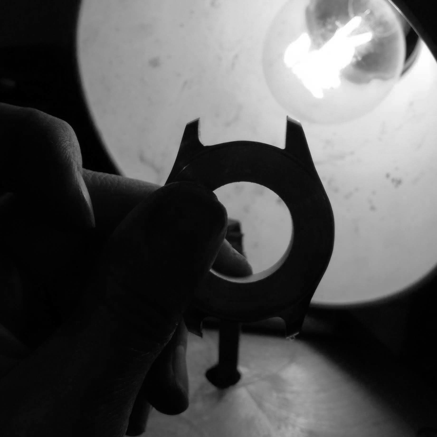
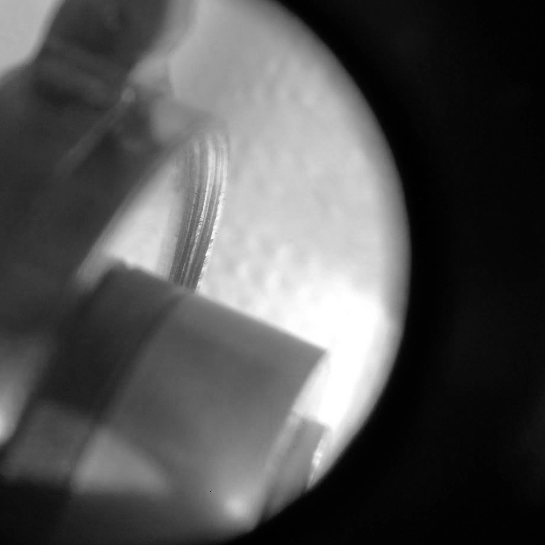
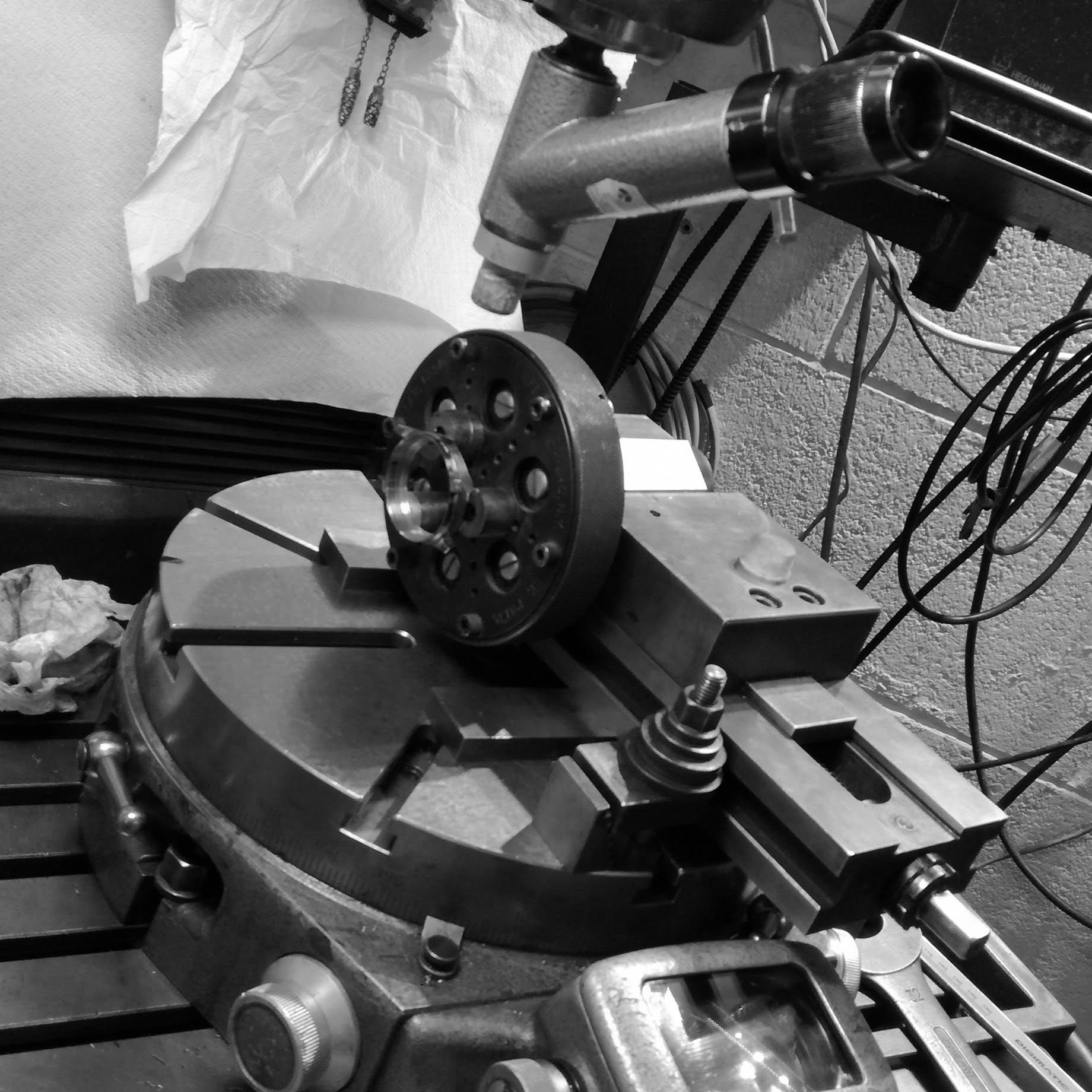
I continue working slowly, using a 10x image of the case outline on the Optical Comparator to make sure it is within specs.
The case on the comparator stage
The kind of finishing achieved with the die filing machine.
The filing leaves a burr on the edges, and this has to be removed very carefully (and slowly) so as not to ruin the profile of the lugs.
The side of the case is sanded and the contour finished with a 400 grit sandpaper. It is placed at a 90-degree angle to maintain case geometry.
You can see the areas on the left lug that still need to be sanded out.
This spot seen is due to the cutter vibrating as it cuts into the stainless 'catching' and moving inwards, it is a defect that needs to sanded out.
Here the sides of the case, brushed, are almost finished. After all other machining steps are done, a final pass is necessary.
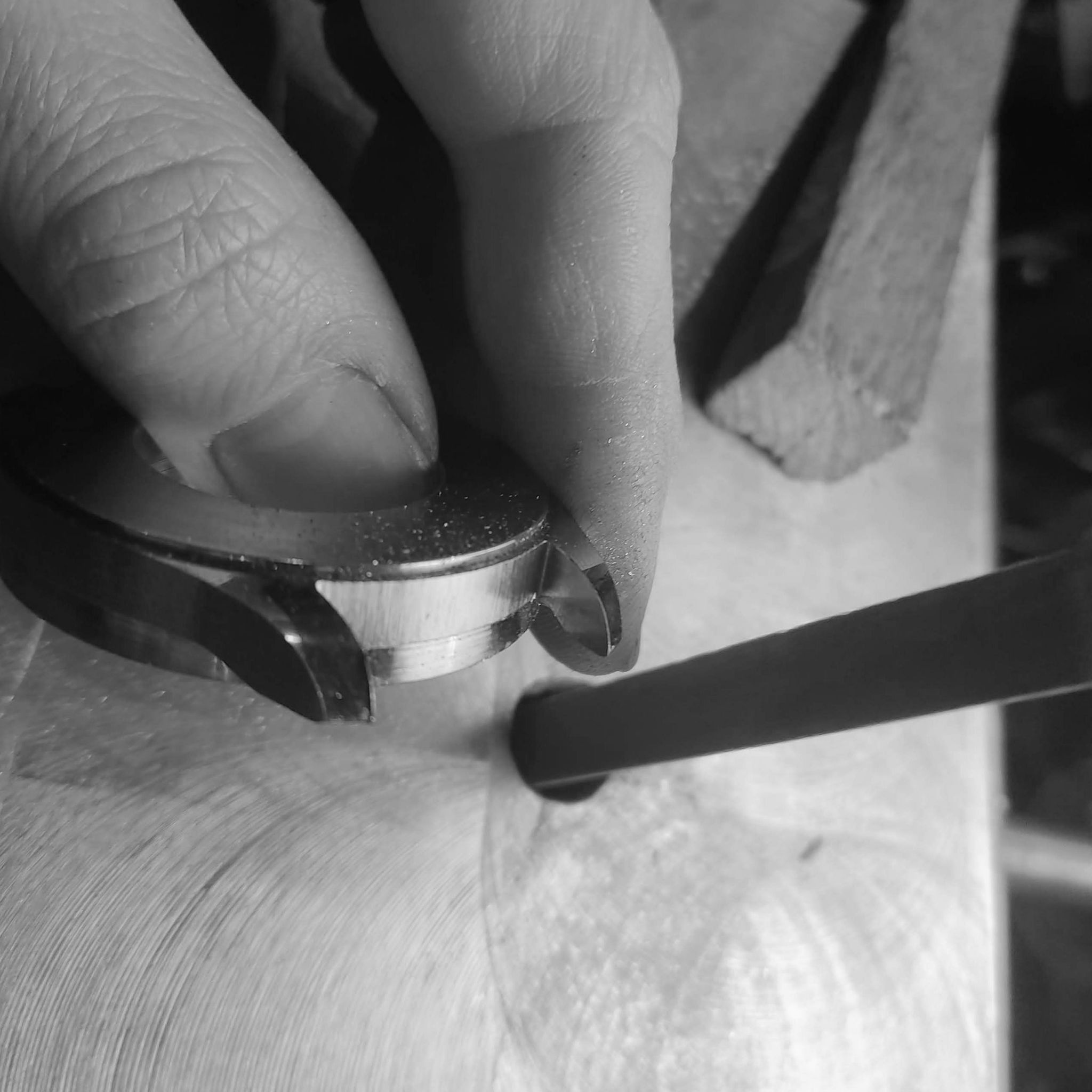
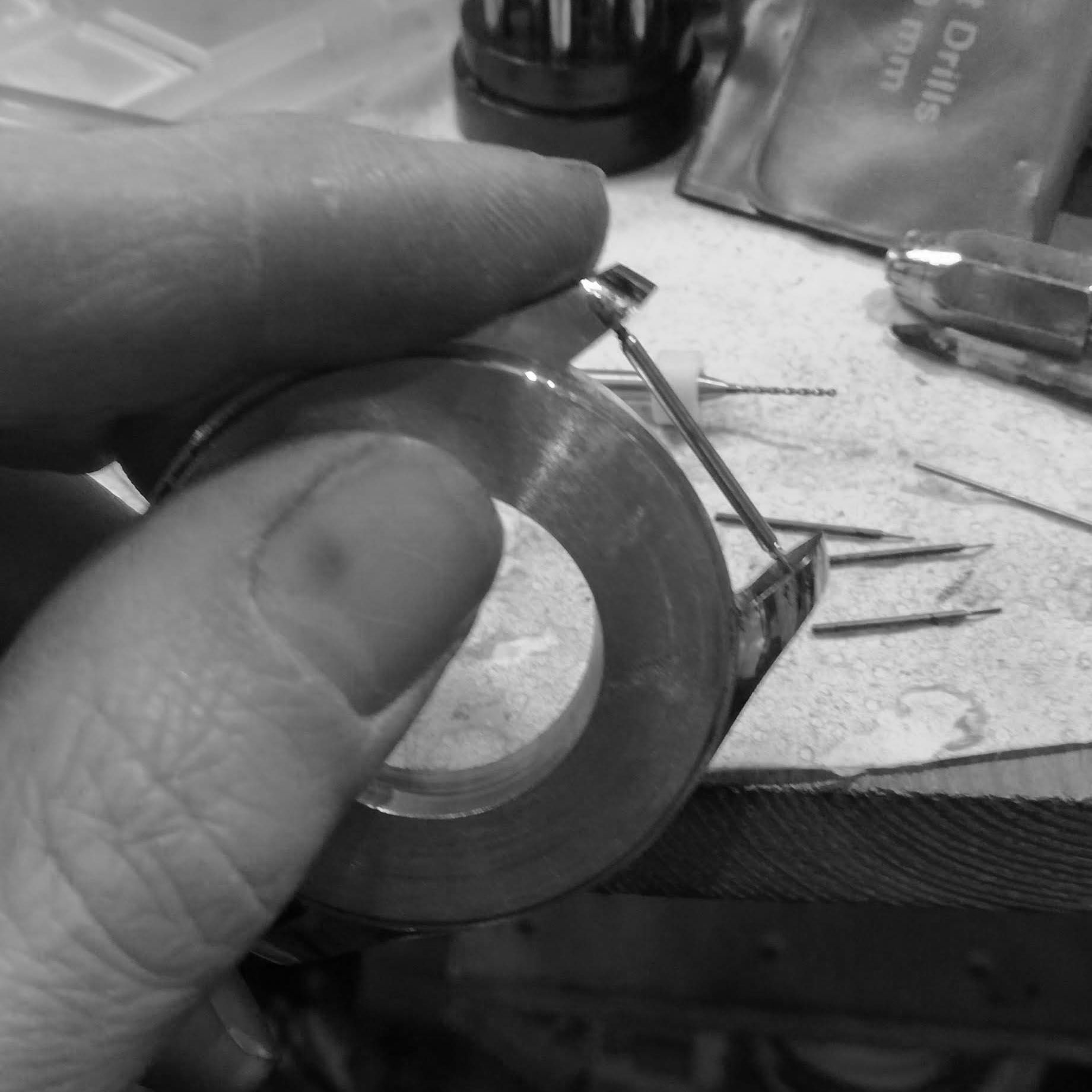
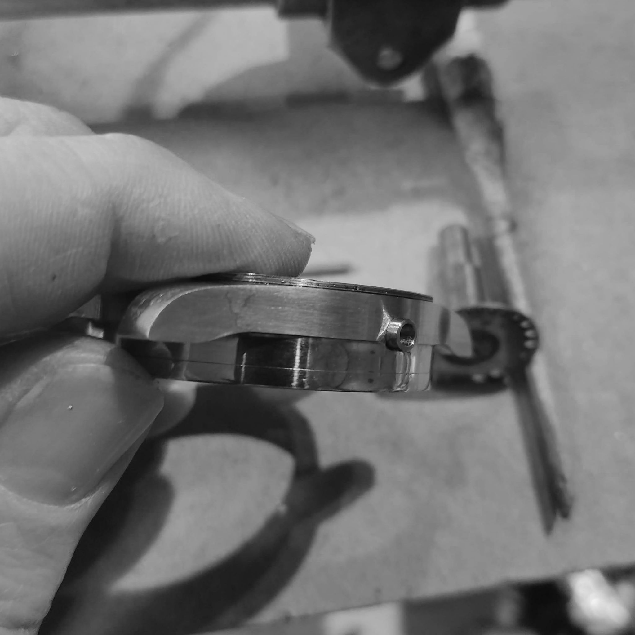
At this point, I drill the spring bar holes.
I start by deciding the height of the strap, and then slowly working a hole at the desired area.
Spring bar in place
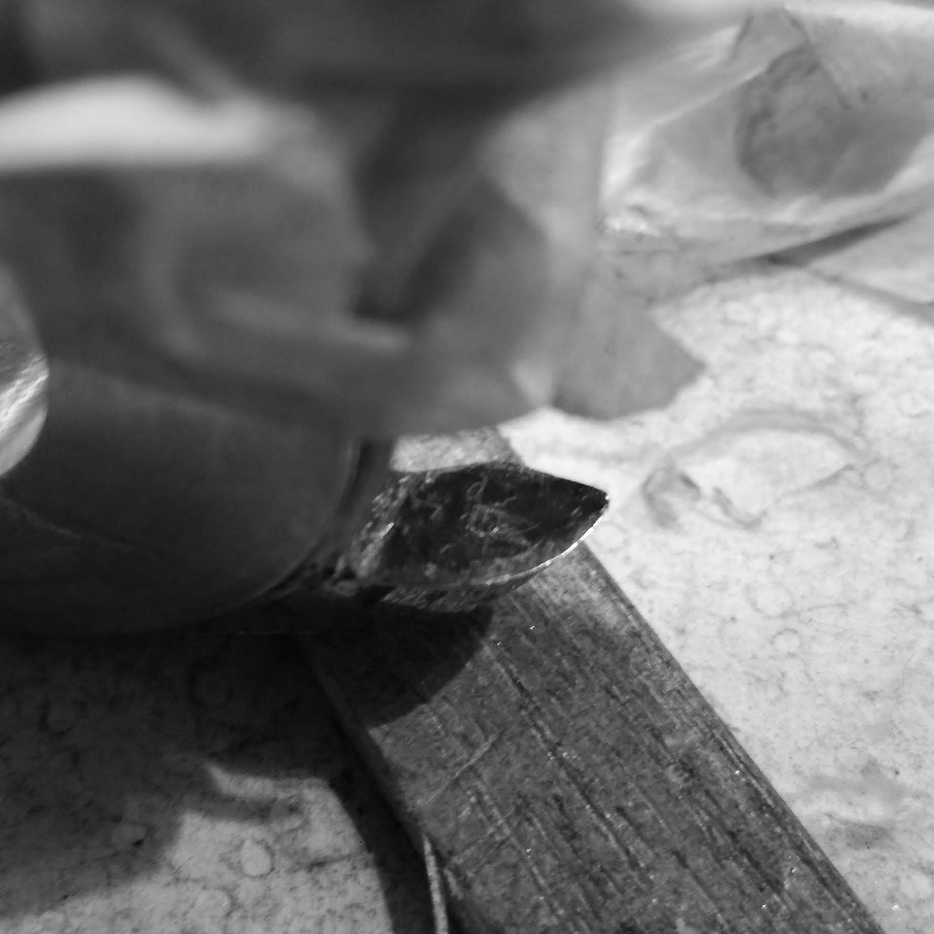
Chamfering the hole.
Spring bars in place.
Next is threading the case to receive the top and bottom bezels, a screw cutting lathe is used.
A thread of 0.4mm per millimeter is chosen.
And the change wheels to cut this thread are installed.
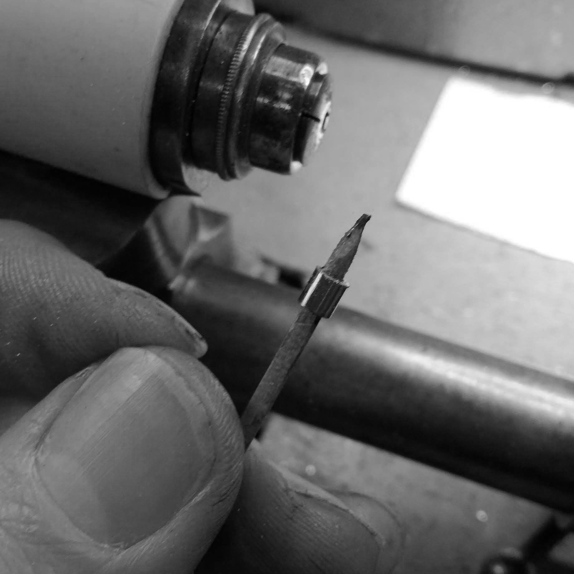
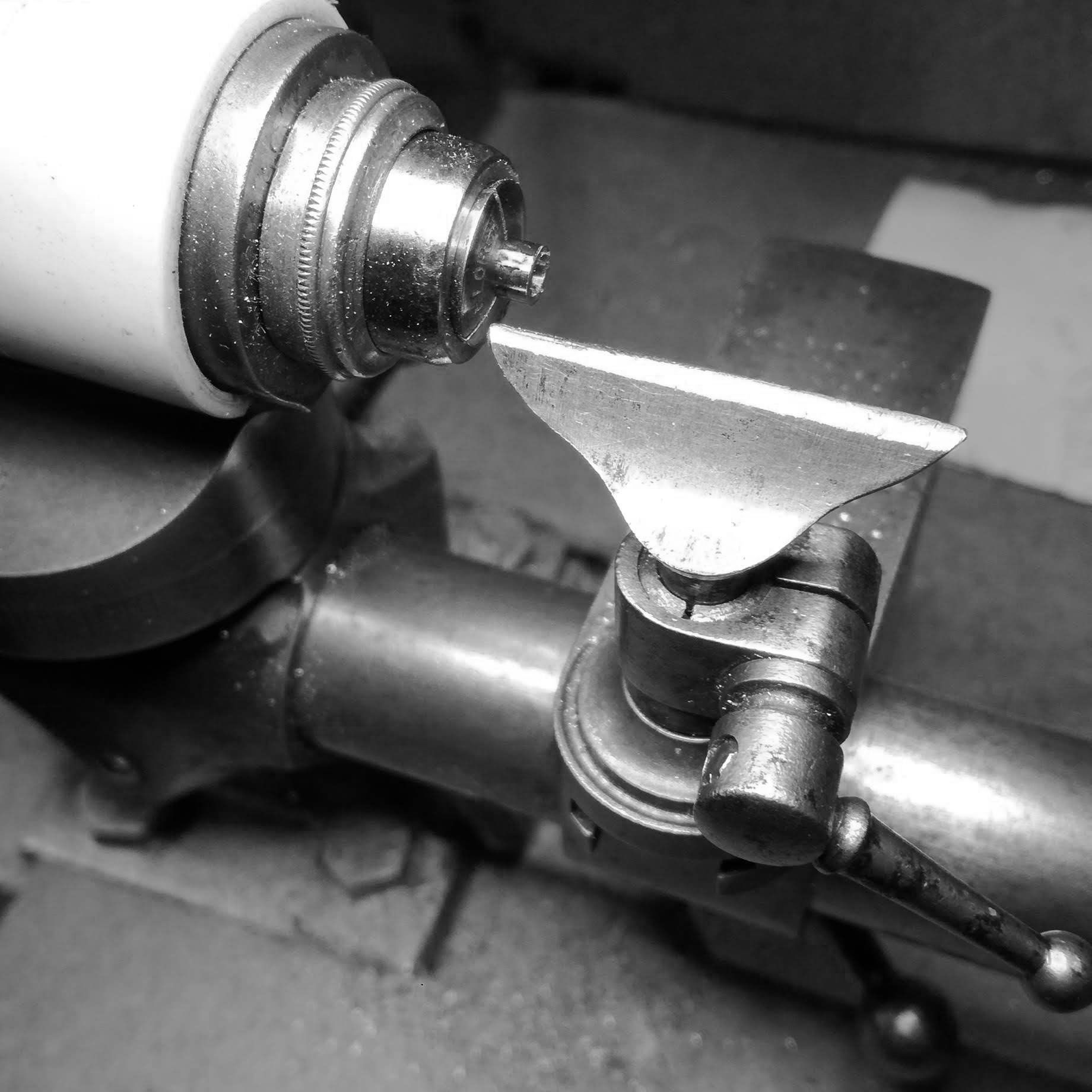
A custom thread cutter is shaped by grinding a cutter to the desired depth.
The top threads are cut.
Next the case is moved to another lathe and the front is machined, in order to work on the back and finish the back of the case.
The case is transferred back onto the screw cutting lathe and the back thread machined.
The back threads. They were polished afterwards.
Further work on the front of the case to final size.
Turning over and cutting out to final size.
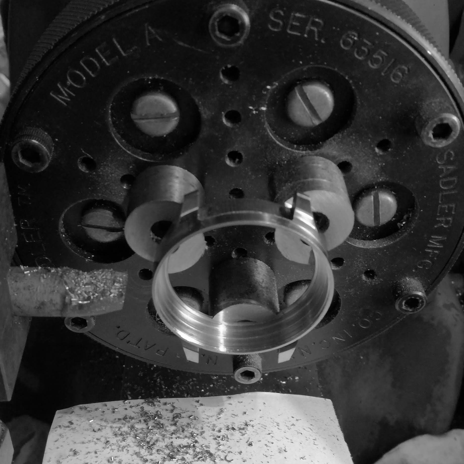
Due to the design of the case, a special expanding collet has to be machined to hold it, and to complete the removal of material from the interior.
Case being machined in the expanding collet.
A few more operations are necessary to complete the interior of the case.
The interior of the case is too thin now and risks ruining the part if I continue holding on to it through the dial side.
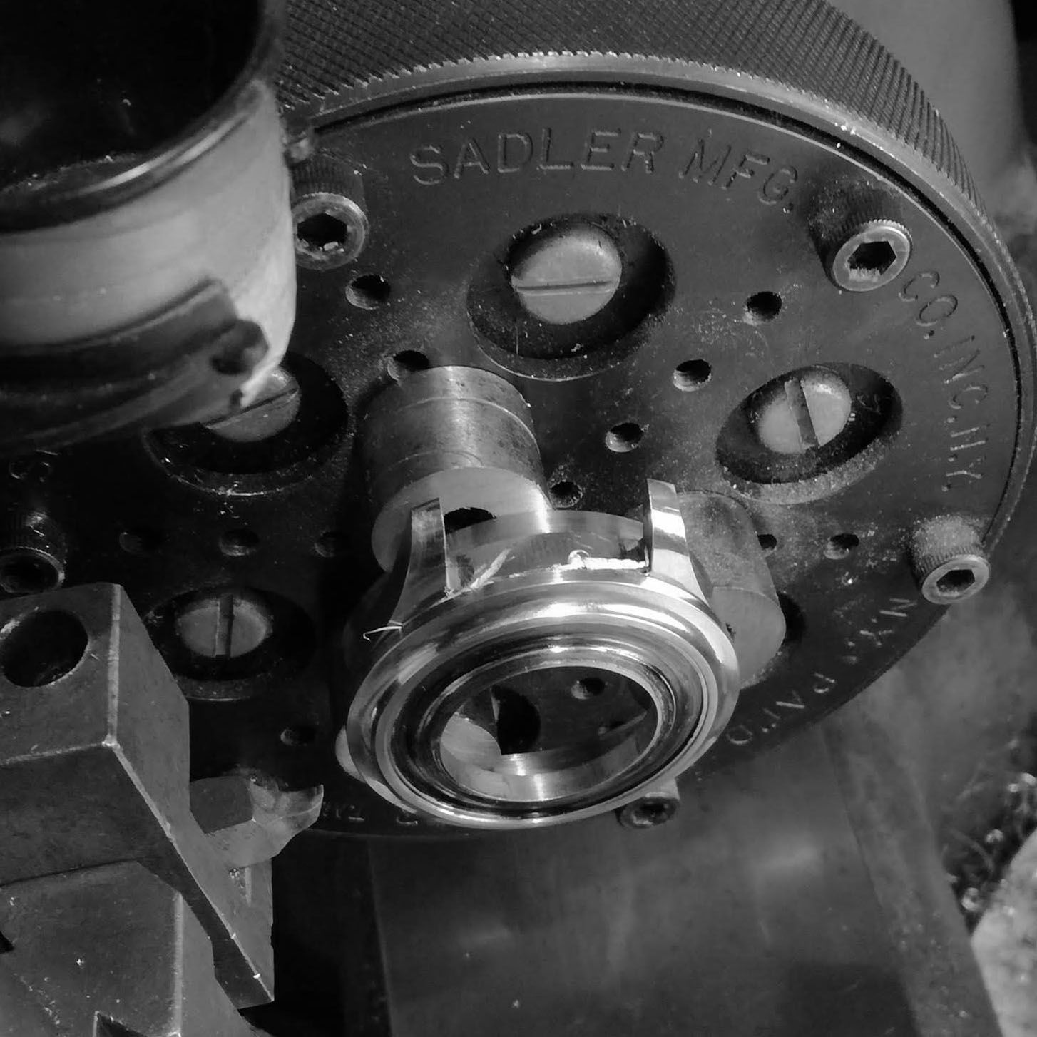
The soft jaws on the Sadler diaphragm chuck are turned to size and the case is held from the back.
Turned the interior diameter to specks, the dial will sit inside this portion of the case.
Another view of the case, starts to look like a proper watch.
Turning the outside back of the case, this will undergo various machining operations to get it to final shape.
Now I start to turn the front bezel of the case from a piece of billet. Lots of material has to be removed to get it down to size.
Further turning of the underside of the bezel.
The bezel is then turned around on the same chuck, I use a ball bearing to get a rough alignment before further adjusting, so that the front and back surfaces are parallel to each other.
Bringing down the front, this is an intermediary step before further machining.
Setting up the front bezel, now turned around again on the expanding chuck, on the screw cutting lathe.
Threading the interior of the bezel. Various passes have to be done in order to cut into the stainless, and not ruin the depth of the threads.
Checking the fit of the threads on the case.
Further checking after another few passes.
The bezel is then taken back to the larger lathe and the profile turned.
I start turning the distinctive, and perhaps the most beautiful feature, the convex fluting on the bezel.
After the curvature is turned correctly, I spend time slowly grinding out the machining marks, so that it will be easier to polish the fluted bezel.
In order to guarantee concentricity between bezel and case, I turn the final dimensions of the outer diameter of bezel on the case itself.
The bezel is then placed on the chuck again, and parted off from the center.
Turning the interior of the bezel now on the case, very light cuts are taken.
I do this on a different chuck, so that the high forces on the bezel to remove material don't ruin the thin case (which is now about 1.5mm in thickness on each side).
A look at the case and bezel wedded together.
Another look with a strap. The bezel has ben given an initial polish on the convex area, polishing this correctly involves various hours.
Turning now the case back from a billet.
The piece was reduced to a size about 2mm in diameter bigger, bored, and parted off. Now boring the interior opening to accept a collet.
Testing the collet to part fit, it has to be a tight fit to ensure concentricity.
The back bezel is then fitted on the hard collet, and the exterior machined to near final size.
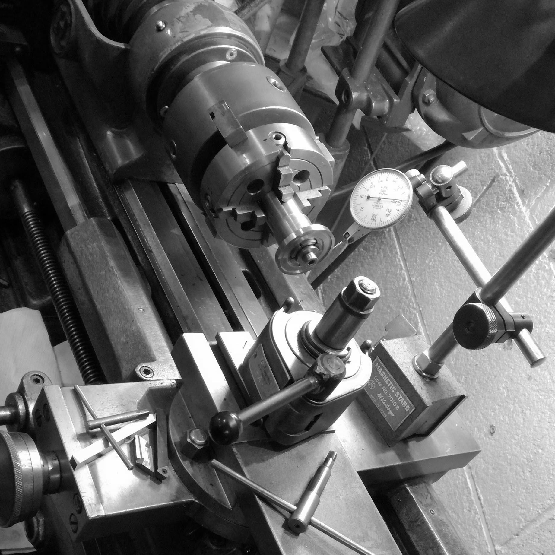
The back of the case is now placed in the threading lathe, and threading of the back bezel started. A micrometer, ensures knowing how deep each cut is (to check against the handslide lead screw dials).
Testing the fit with the case before removing the back from the chuck.
Coarse diamond paste is inserted between the back and case, and successively screwed and unscrewed so that the threads grind against each other, and ensures smooth clean action between thread surfaces.
The case back outer diameter is screwed onto the case, and turned together to ensure visual concentricity.
This turning is very slow, since very light cuts (near 0.2mm) are taken, so that the high torque it suffers doesn't ruin the thin case and threads which acts as the holding agent for the back bezel.
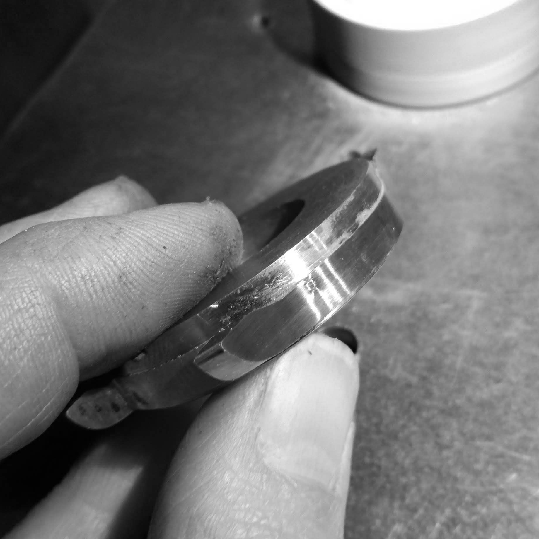
I start modifying the case division, reducing the diameter of the bottom portion, which will be polished and thus contrast with the matte finish of the top portion. Creating a visually lighter case, and diminishing the sense of thickness.
Now a lot of polishing is done to remove the machining marks. Since the case is so thin, it tends to chatter when presented with the cutting tool and this has to be slowly ground away.
Turning more of the case back on the case itself.
A look at the case with the back portion polished, and the bezel.
Turning out the interior of the case back. Many and very light cuts taken to not ruin the threads or main case.
Further turning.
Outer shape near final. But the overall thickness of the case will be reduced once other parts are finished.
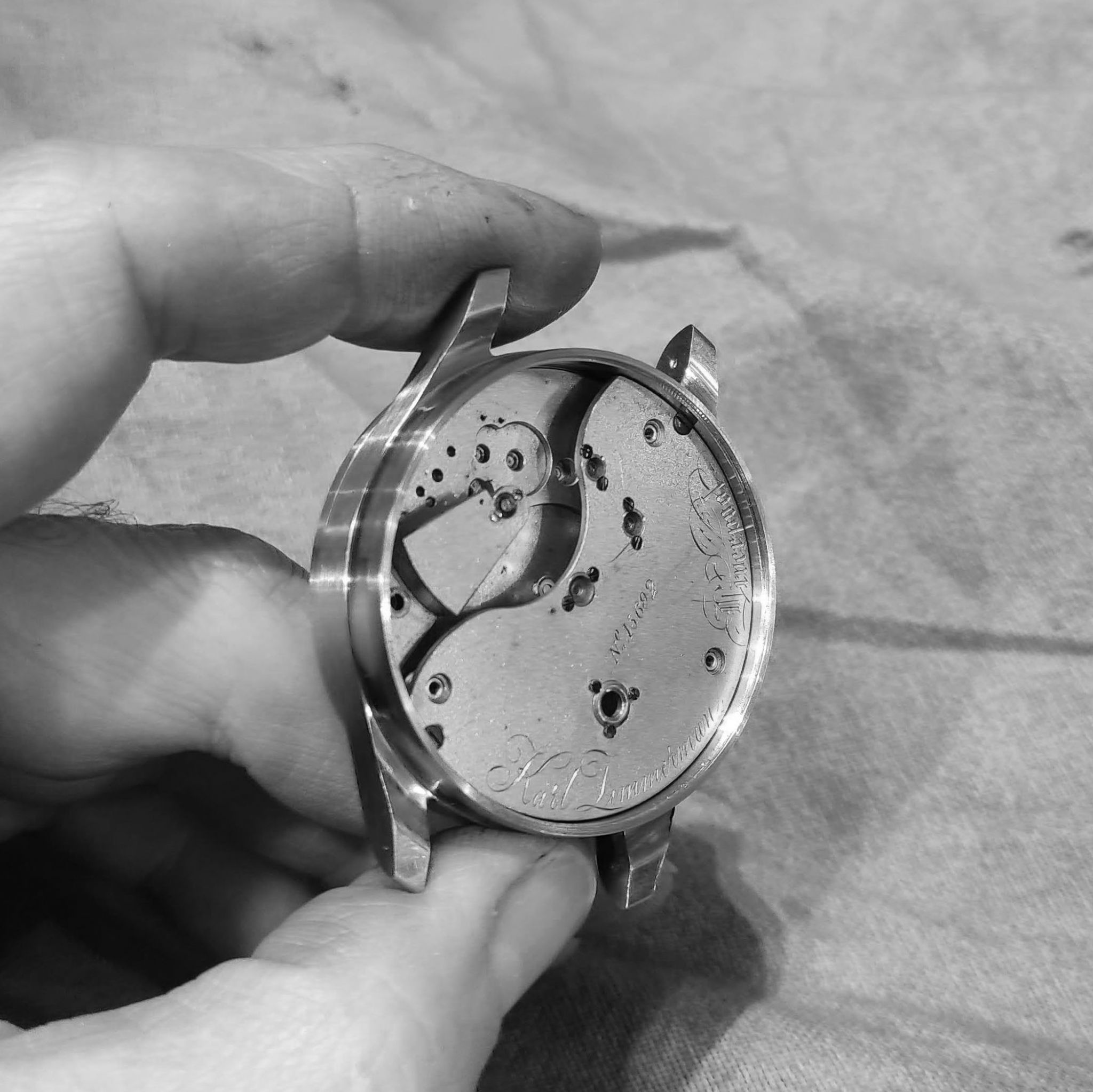
First look at how the watch looks in the case.
A look at how it sits on the wrist.
Polishing step of the outer ring on the front bezel.
Polishing again, spending over three days on polishing out the machining marks from the case back.
Not fully polished caseback but close. The slightest mistake in pressure ruins the process and coarser grit has to be applied and the process renewed.
The reason the caseback area is time consuming is that the geometry of the lugs do not permit reaching the area with any polishing wheels, so it has to be done manually, and slowly. A brighter cleaner finish will be reached on the case back area.
The case with a 'head on' view.
Now that the exterior of the case is nearly finished, some machining of the interior is necessary.
I mill various recesses in the case. since the case is so thin, it is of utmost importance that tolerances are within 1/100th of a milimeter.
Cutting the slot for the rocking bridge center wheel. It is slightly larger than the movement diameter.
The center wheel recesses into the case, it is above the area where the winding stem hole will go.
Now, a small recess need to be made for the mainspring barrel teeth, this is precautionary, but if for any reason the movement itself moves there might be a possibility of touching and ruining the barrel.
Using vintage thickness calipers to measure thickness of the small recess.
I cut it in successive operations, since the blade never runs perfectly eccentrically and can cut more than what one calculates based on it's outer diameter. Here I am cutting a slot for the movement holding screw.
Then I locate the case in the jig borer to drill the stem hole. Preparation for this took a lot of time as I have to make sure the hole will be perfectly tangential to the center axis of the case.
Drilling takes place slowly, with a successive set of drills to arrive at the final size.
Spot center drilling at high speed.
Since stainless tends to gum up when cut and deform, I slowly drill out to final size.
Besides each successive tool change, the presence of the case holder diaphragm chuck, creates problems for the spindle to reach to the correct place, so a series of tool holders with thinner diameter are used.
There is very little clearance, but sufficient to reach.
A simple hole, took the better part of a day to locate and drill.
This was the first half of now having to clean up the interior of the case from swarf still stuck to the interior of the hole.
And the outside is rebrushed again.
And the bottom section of the case needs to be cleaned up, I tape up the whole case so that the hand files only attack the border of the hole.
Using a ruby file to clean up the area.
Nonetheless, another 2 hours of polishing were necessary. Since a recess was formed, and I had to slightly adjust the entire bottom area so that there wouldn't be any visible deformations around the case hole.
Now I start the stem tube.
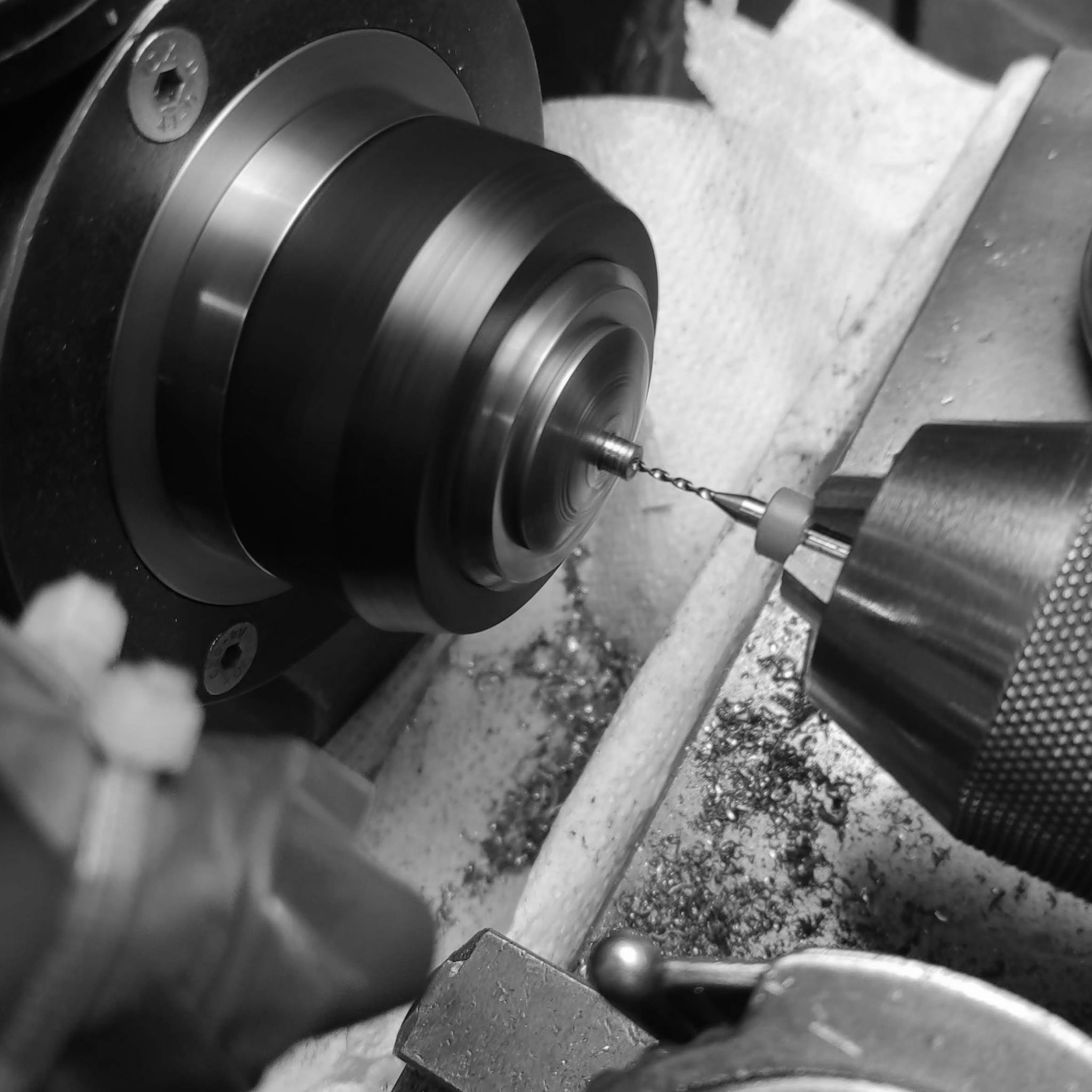
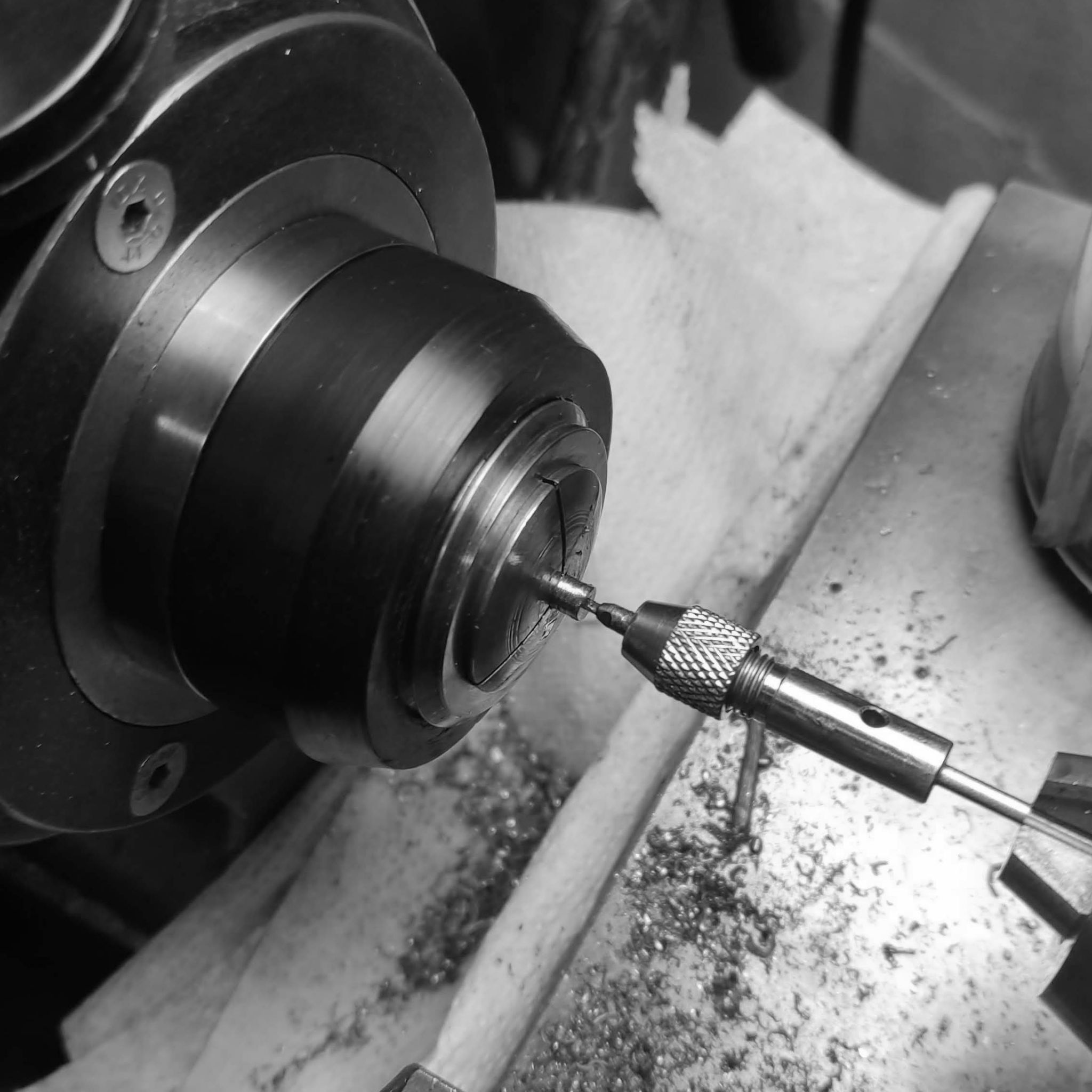
After center drilling to give the piece a guide, I drill the hole in successive steps, so that the drill does not 'walk' and drill off center.
Further drilling.
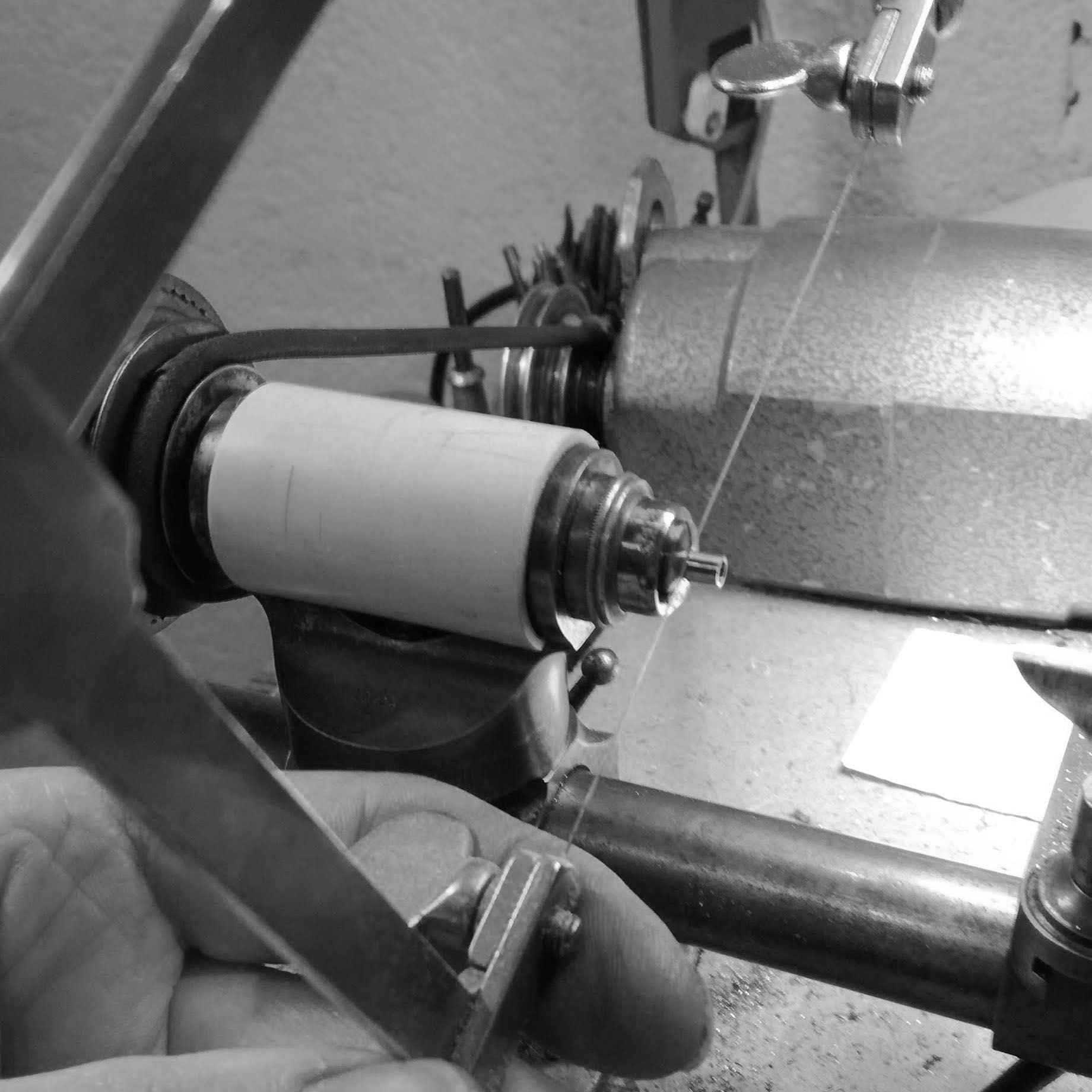
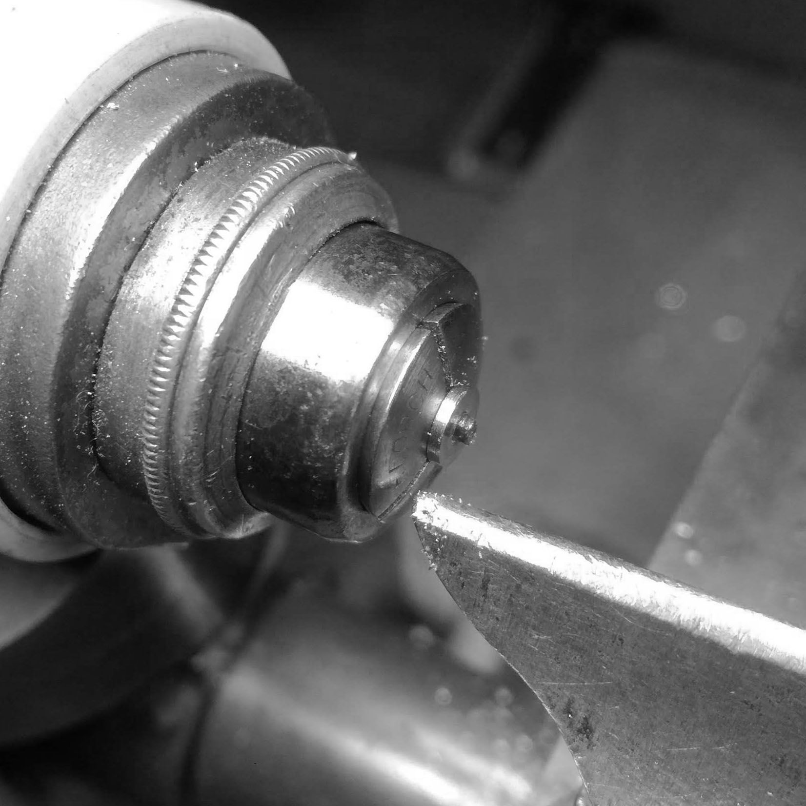
Then, in order to get a good finish, I turn on the watchmakers lathe, with hand gravers which are mirror lapped, thereby creating a very clean finished surface.
The interior of the hole is beveled with a vintage countersink tool (as used on movement jewel decoration).
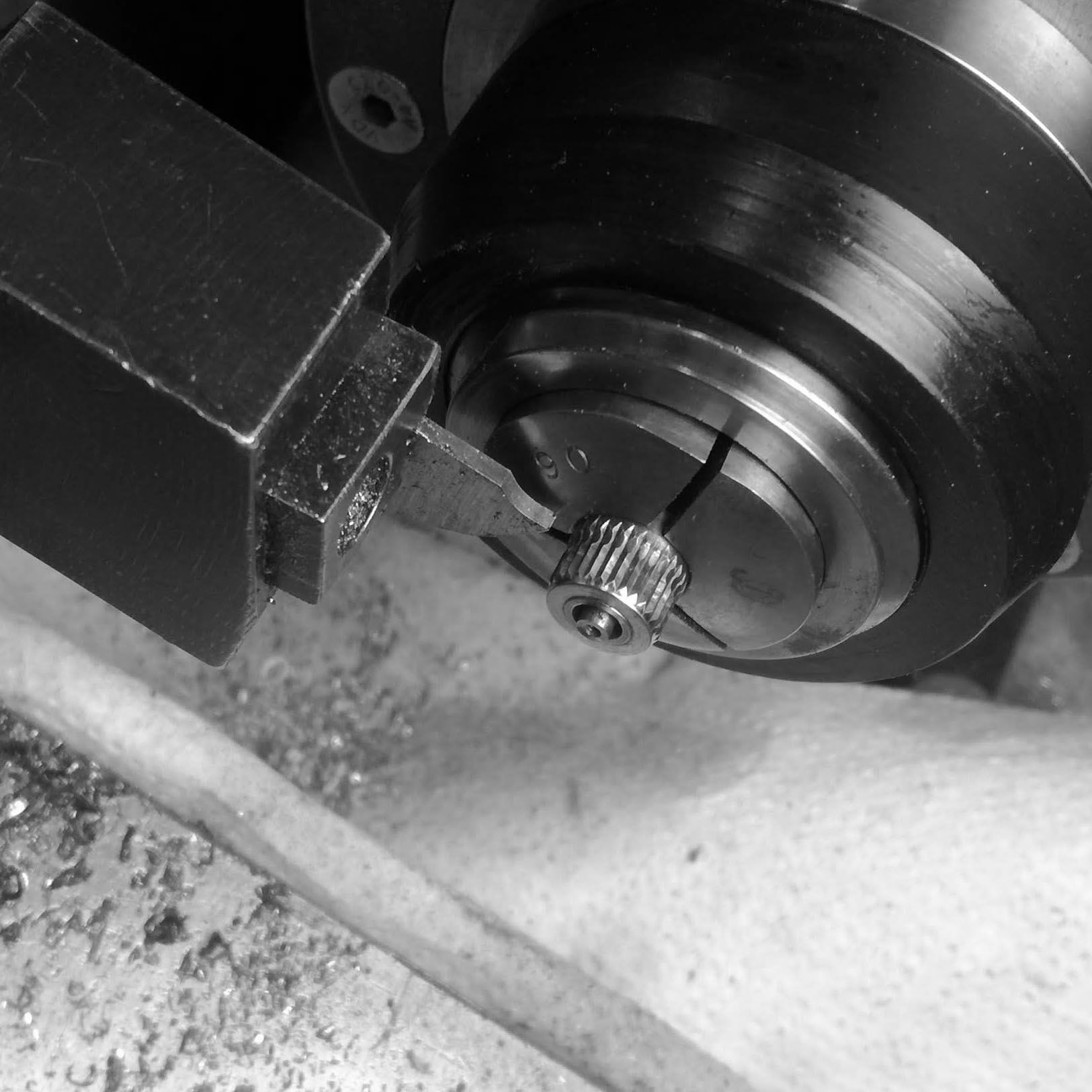
I cut off with a saw the part.
Before last cuts are taken I ensure that the part does not fly off by keeping a piece of wood inside.
Further finishing of the taper, it has to have a 0.01mm difference between hole and diameter so that it can be a press fit.
The case tube before fitting.
After pressing the case tube.
The case tube projects inside, and also, in order to have clearance for the winding gear, a recess has to be milled in the case. I will use a horizontal spindle on the case, in order to save time. To do this, I have to modify the spindle to take a direct drive (I normally use this spindle for sharpening cutters on the tool griniding machine).
An acetal plug is machined to allow the collet closer to be used without the indexing wheel it normally has.
Fitting the draw bar to the plug.
A view of the setup.
I now machine a plug to be secured to the draw bar, so that if connected to a motor via an extension, it will drive the spindle.
The plug, with spigot.
Through drilled and tapped on the jig borer.
Crudely fixed with a screw for this temporary operation.
Milling a recess around the perimeter of the case, to give space for the winding gear. Tolerances are tight, since I am now leaving less than .5mm of thickness on this portion of the case.
The setup after machining the recess (which is done in various steps, each time controlling final thickness).
Here I am doing a small brass jig to hold the winding stem before the crown is completed, and can therefore test how the winding action is.
The winding block needs modification, and I grind it to test if it is still usable.
The winding is tested, it is useful, but a bit finicky, and I will make a new winding block, adjusting the height of the support for the winding stem gear (visible is the brass winding stem jig I made).
Before starting that work, I thread one of the dial holes, which will be used to receive the movement holding screw.
Here one can see the threaded hole, and the milled recess where the screw will make sure the movement does not move axially in the case.
Turning the large diameter holding screw from raw stock.
Threading the screw.
Centering the spindle and cuter to each other, in order to slot the screw head.
A view of the small watchmaker's spindle used as an indexing device on the larger mill.
Slotting.
The slotted rough screw head.
Testing the screw position. A cutout has to be performed so the movement slides in, and the screw then turned and holds the case.
As can be seen here, the screw has been given a sharp outer bevel, and partially cut, so that it can perform in this manner. This is typical design for English watches. I purposely do not use the original case-holding screws on the top 3/4 plate, since it is not aesthetically pleasing (more on this in future).
The head of the screw is polished. This will be covered under the open dial.
Polishing the screw. It is then hardened, and the repolished for a final finish (hardened screws polish to a much higher degree than non-hardened metal).
I start work on a new winding gear/stem holding block.
It is milled from a sheet of Oil 1 steel, which hardens to particularly high degree.
After drilling the holding hole, the part is cut off.
Tested on the watch for initial fit.
With a specially made spigot, that goes through the stem hole I test the correct height of the holding block.
With the spigot I locate the center hole of the block and then drilled it on the jig borer.
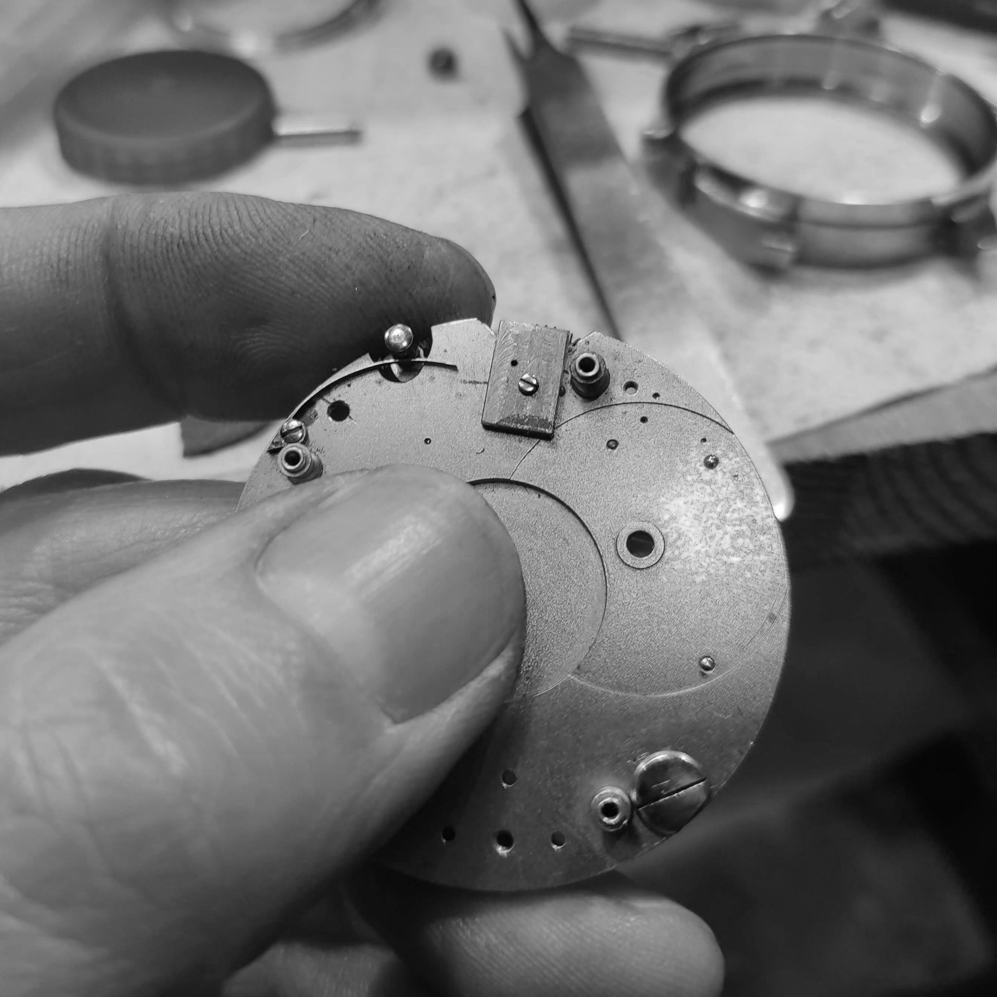
After this, I dill a new movement position locating pin, so that the movement will always fit in the case in the correct position. I took out the original two locating pins, since they don't conform to the new case design.
New brass pin is inserted. These holes are often seen in vintage movements, and are used by case makers when making final adjustments to the case (since movement and cases were often sold separately at a jewelry store, and then after purchase married together for consignment to the client).
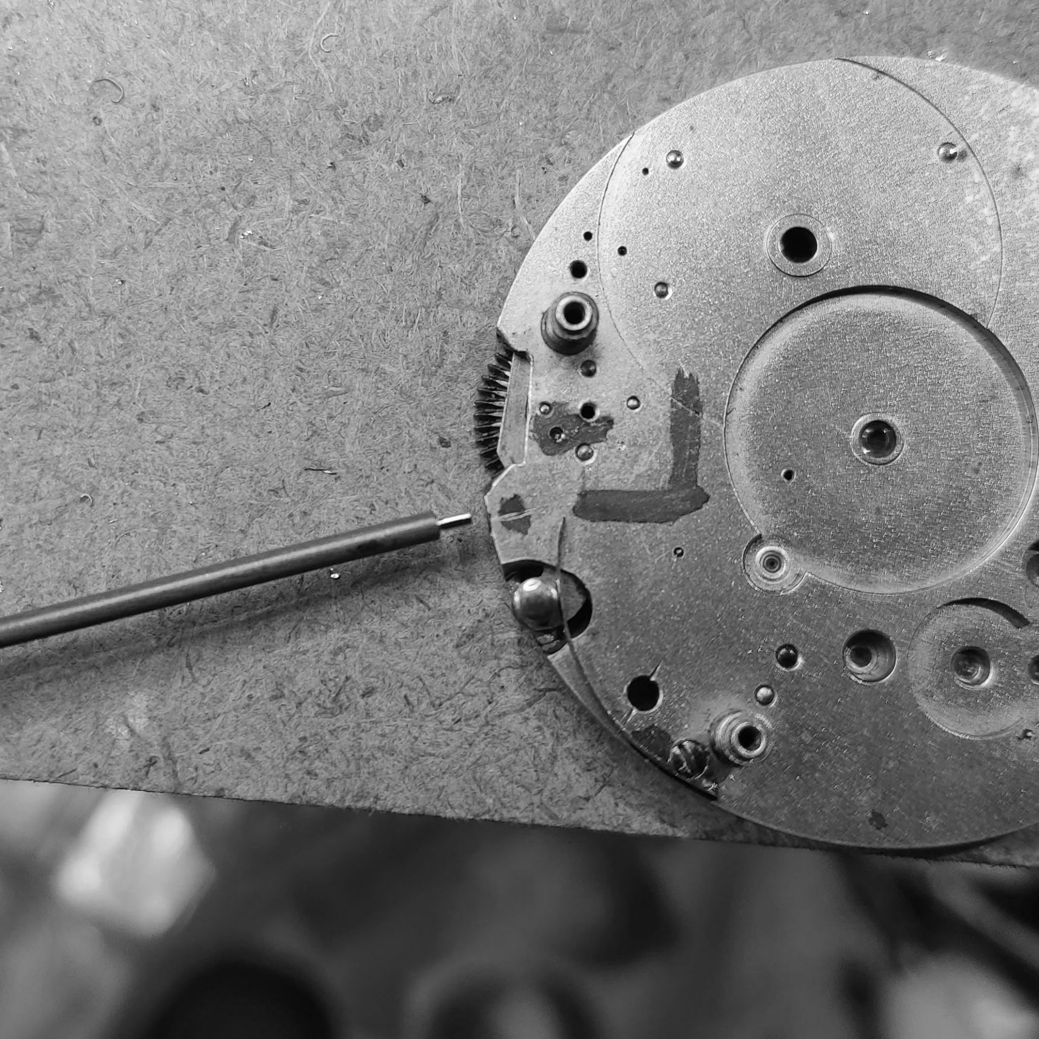
The case itself took a small recess, which was engraved with hand cutters. A veritcal slot has to be cut away, so the movement can be slid inside the case at an angle, and not move in a circular manner in the case.
After determining the depth and area for the time setting stem, it is located and cut in the jig borer.
Since the hole is at an angle to the circumference, I have to mill the hole with an end mill, and progress is slow so that the milling cutter does not 'walk' on the piece (i.e., drill off the intended area).
The drilled hole.
This is given a slight bevel with a countersink tool in correct diameter.
Now I turn the push pin for setting the time.
Further turning on the wachmaker's lathe.
Cutting off.
The push pin.
The back area is adjusted.
The push pin inside the movement.
As can be seen by the intermediary wheel between the mainspring ratchet (top) and rocking lever center wheel (right most) the intermediary wheel does not engage sufficiently.
After adjustment of the push pin, we can see that the gears engage properly, and won't skip under winding pressure.
Now, since the winding and setting are adjusted, I turn to hardening the winding stem. I put it in a small tube, and cover with coal dust, so that it inhibits scaling on the part.
Heated to cherry red and then dropped in the oil for quenching.
The part after quenching.
Tempered to a blue, in order for the teeth not to shatter after hardening.
Initial finishing of the part after bluing.
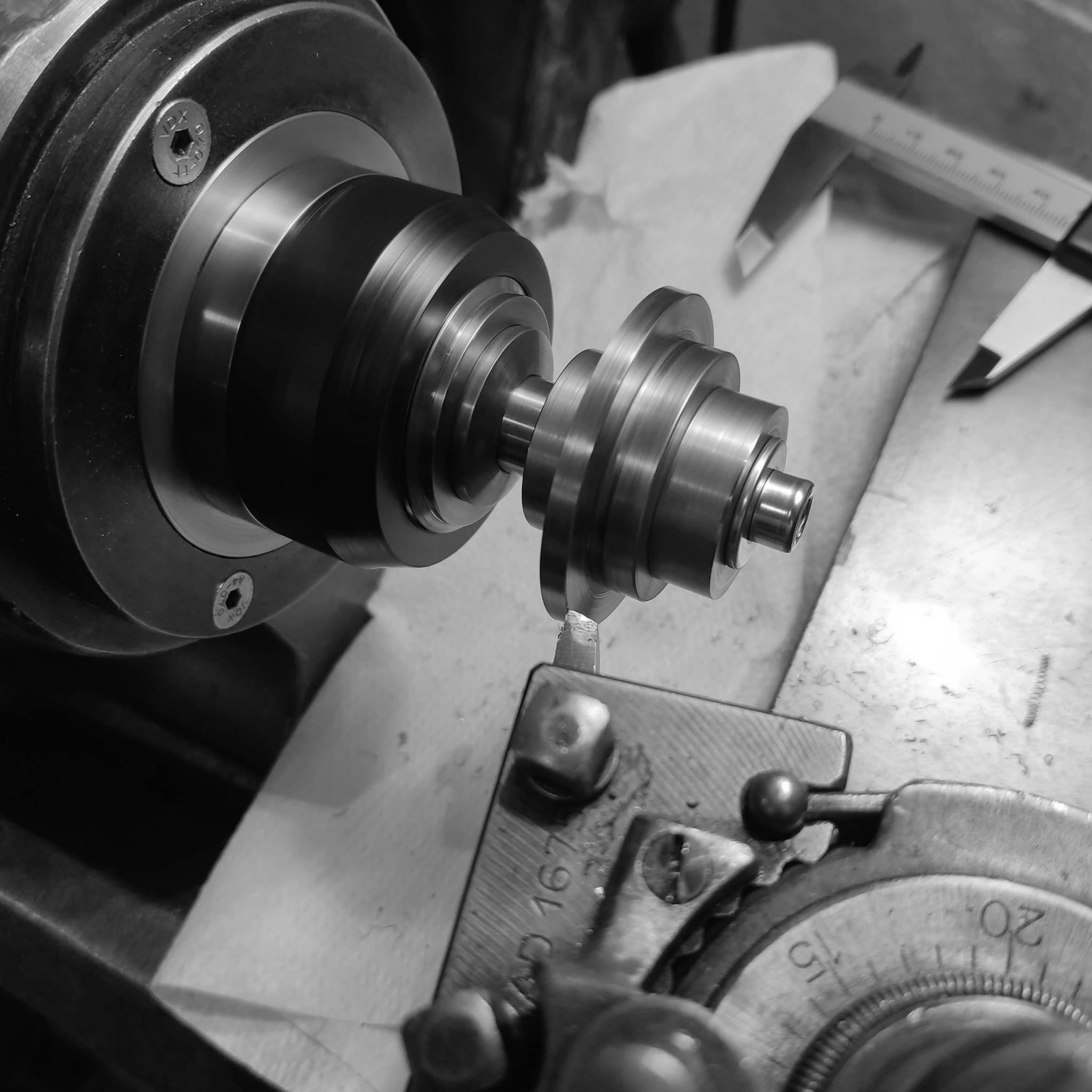
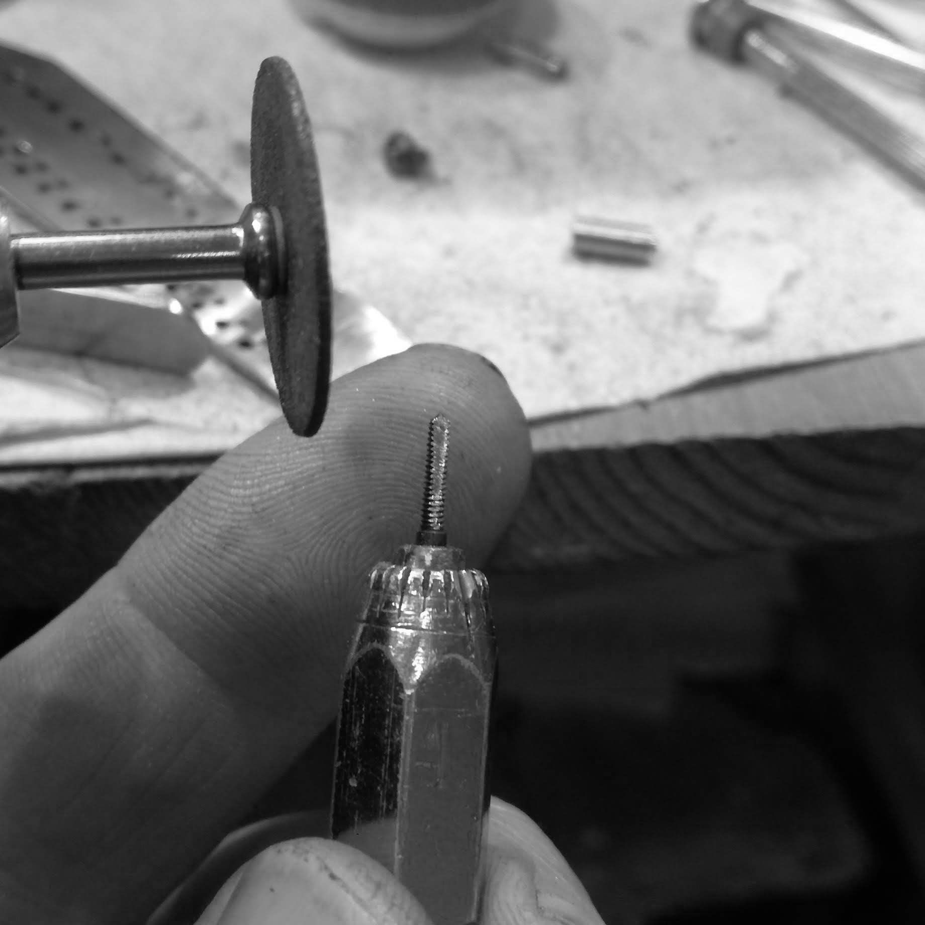
Now I turn towards making the crown itself. This is the interior crown tube. I do this in 2 parts, in order to reduce machining time, and to increase precision.
I make a specialized tap, for the threads, as the tap I have is not adequate for stainless steel.
I harden the tap.
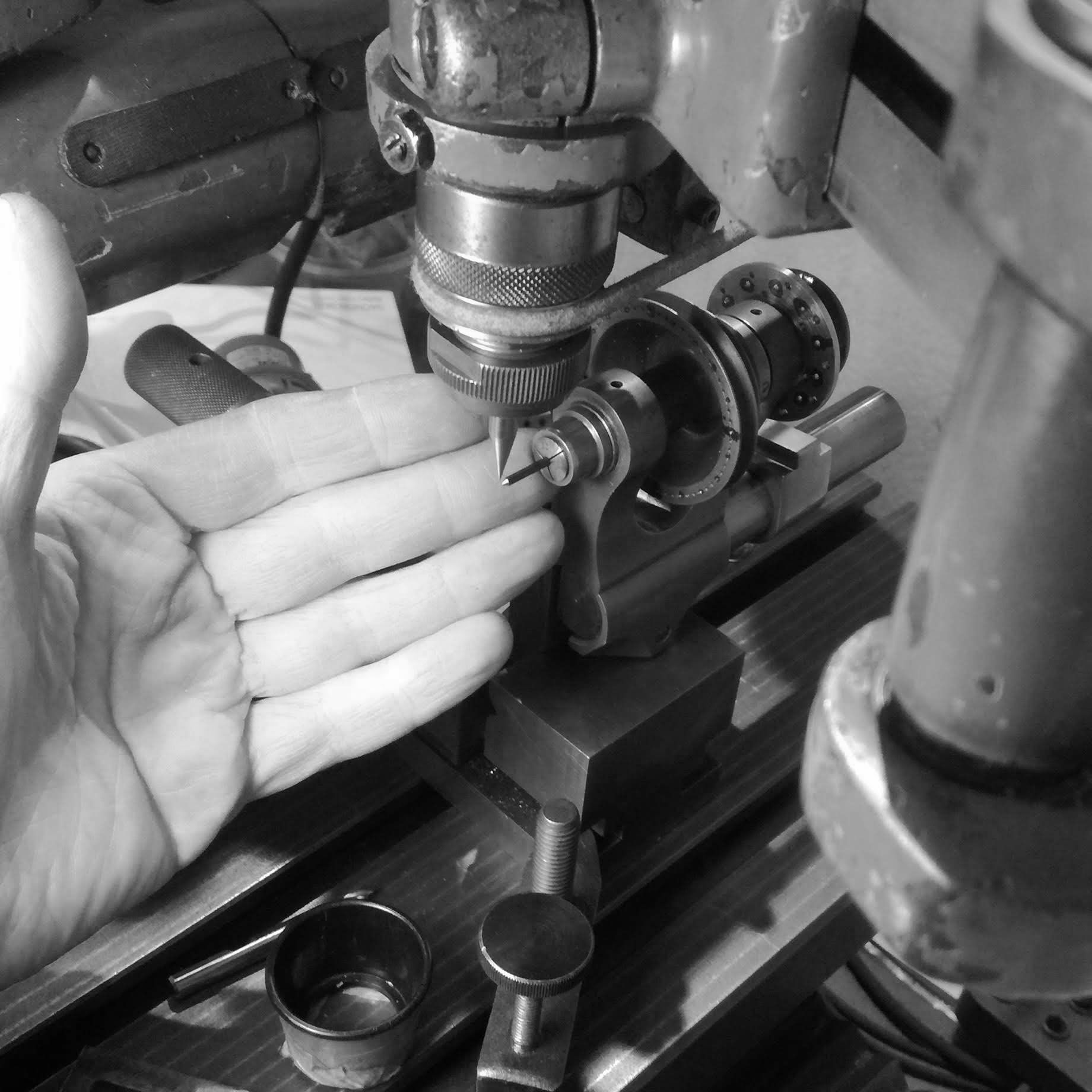
Then I grind the profile.
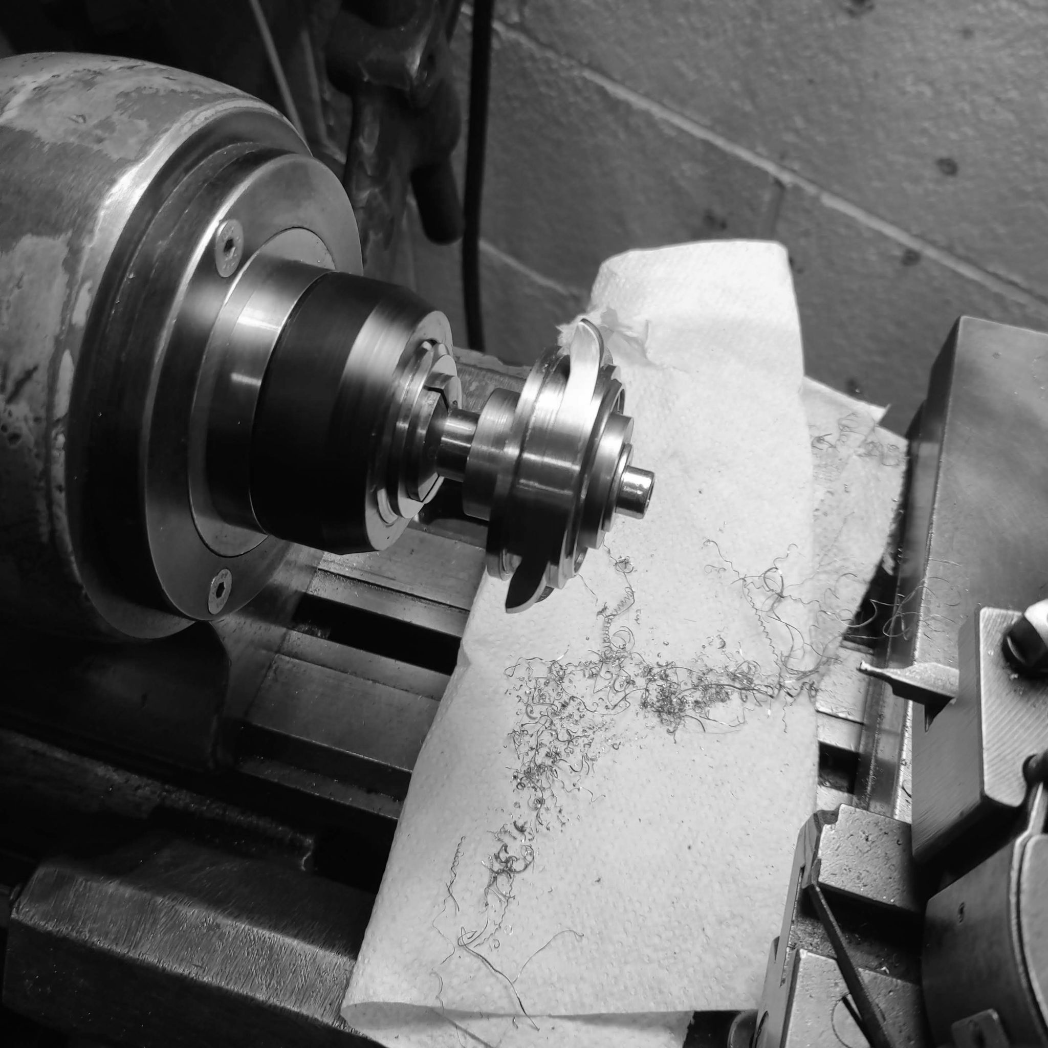
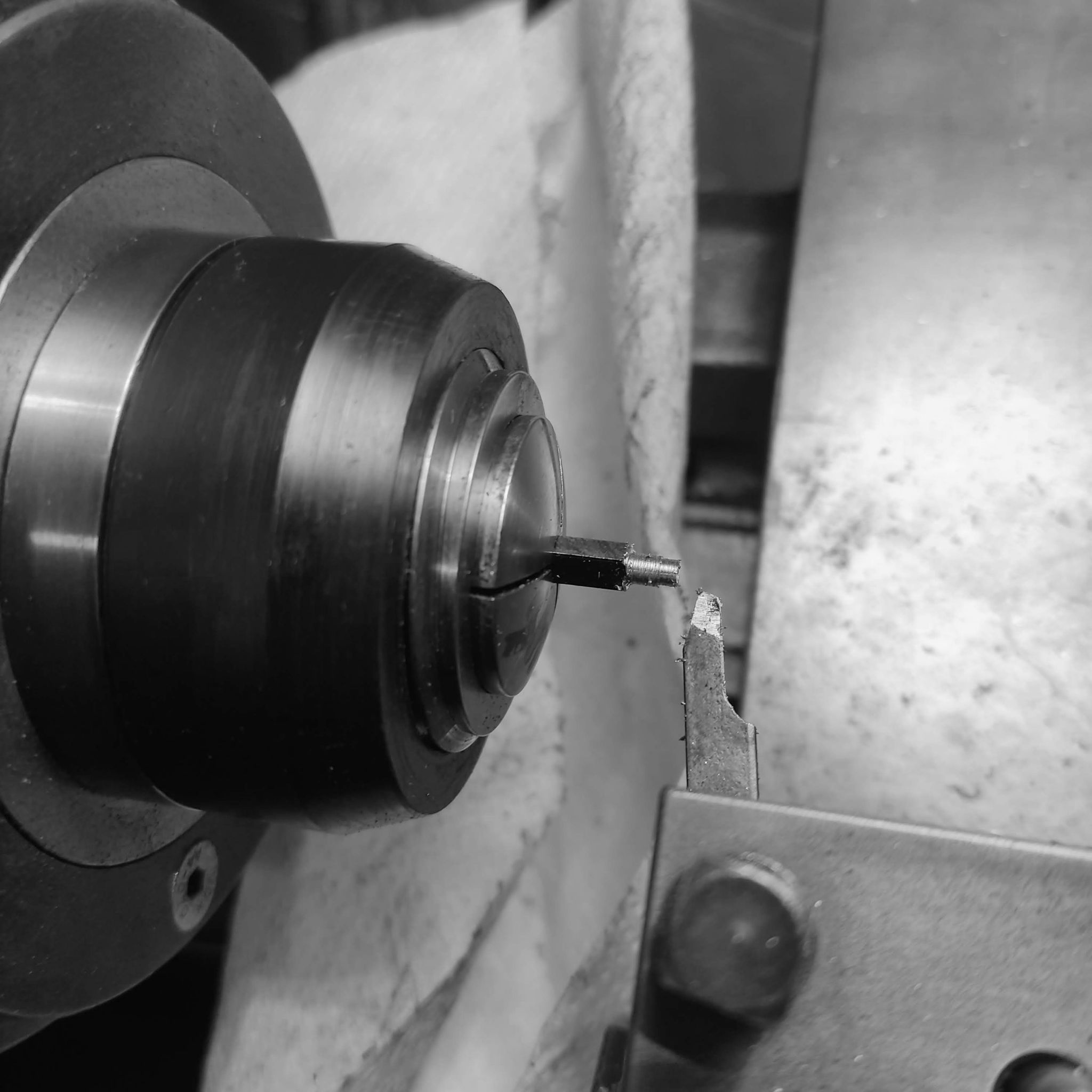
I start to turn the crown tube.
In the process of tapping, the tap broke. The hole was too small, and created too much resistance for the tap.
A new piece is started again.
And a new tap made since the remaining portion of the tap I had made, is being deformed as it threads (not tempered correctly).
Making the new tap, this time from harder oil hardening steel, instead of water hardening steel (this latter reaches a lower Rockwell hardness level).
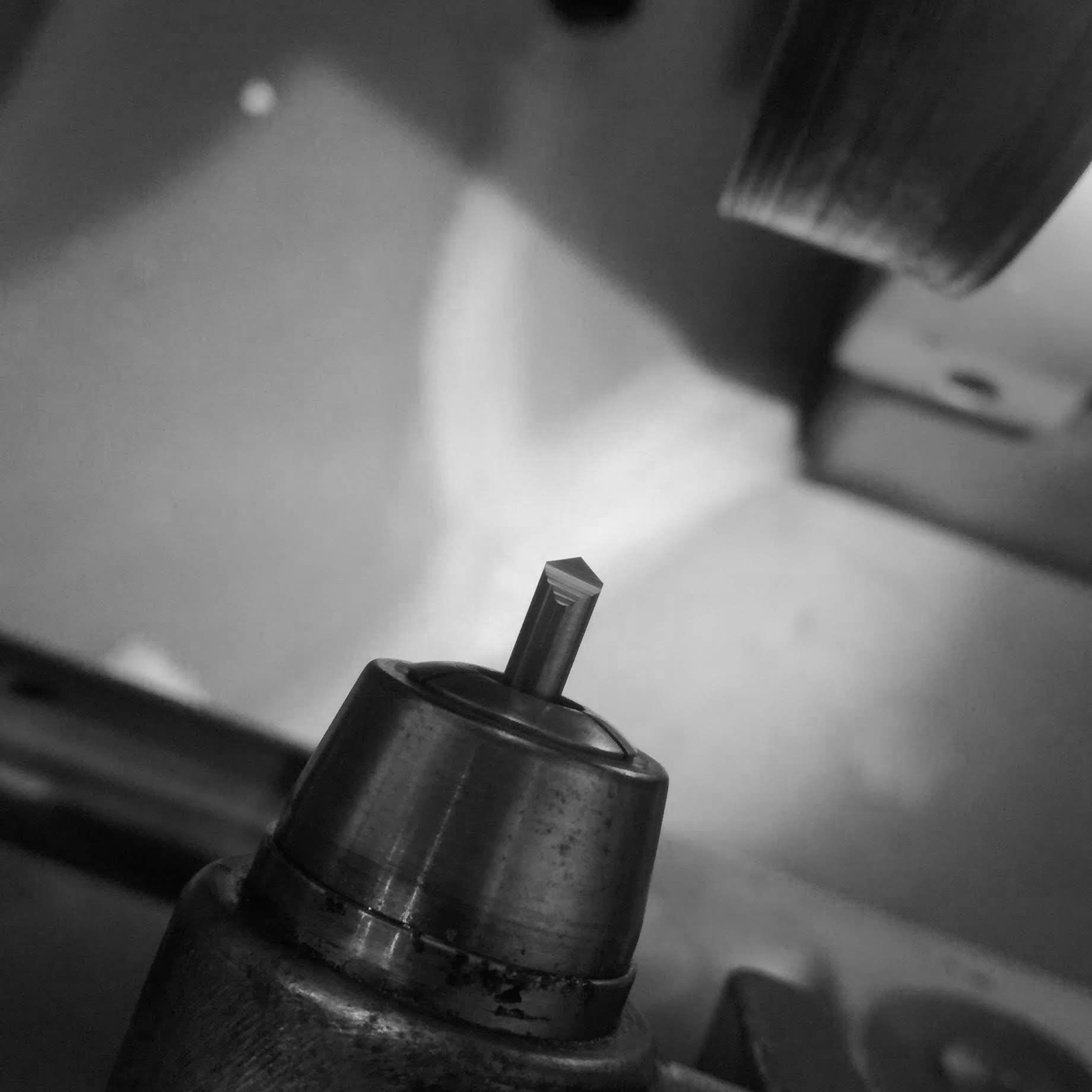
The new tap.
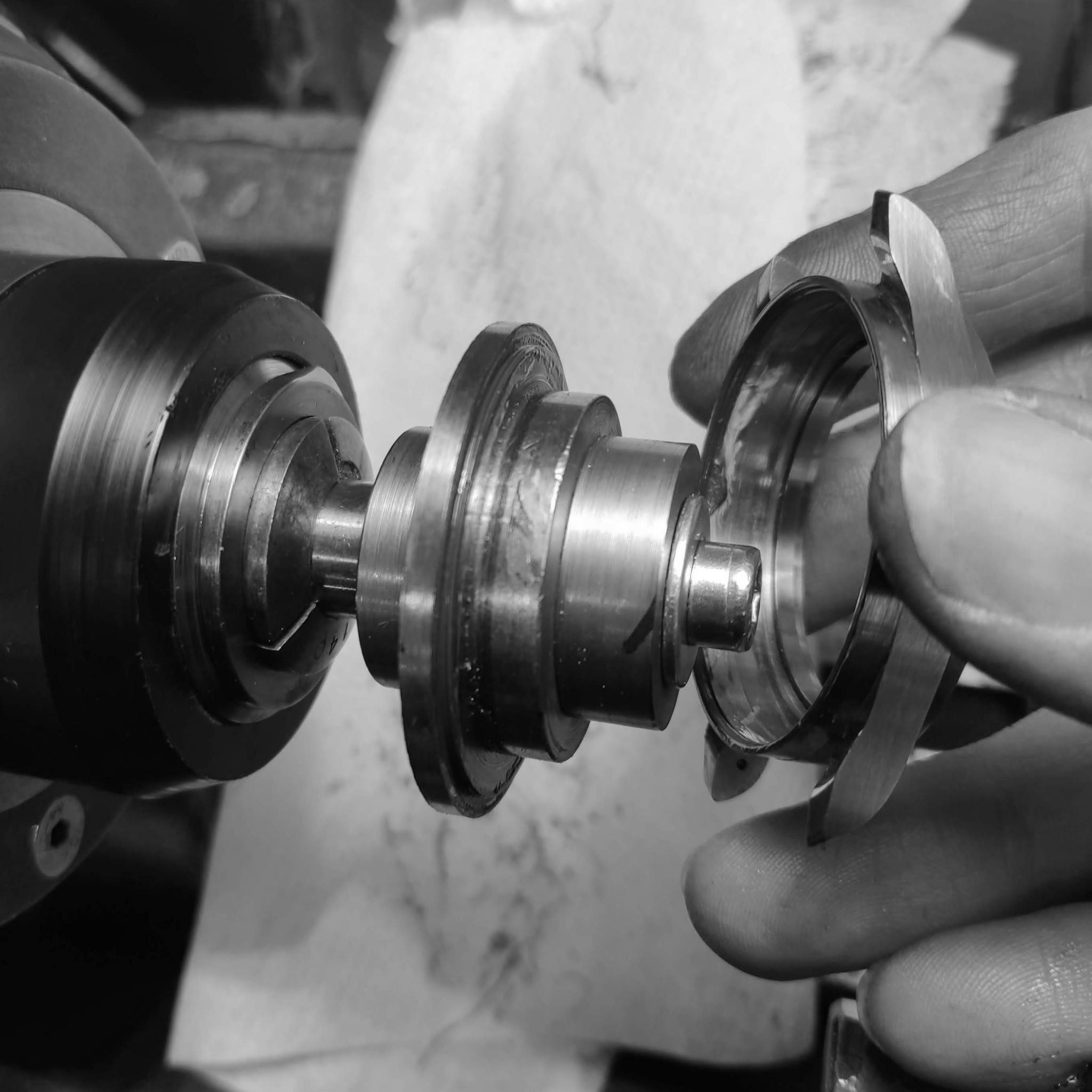
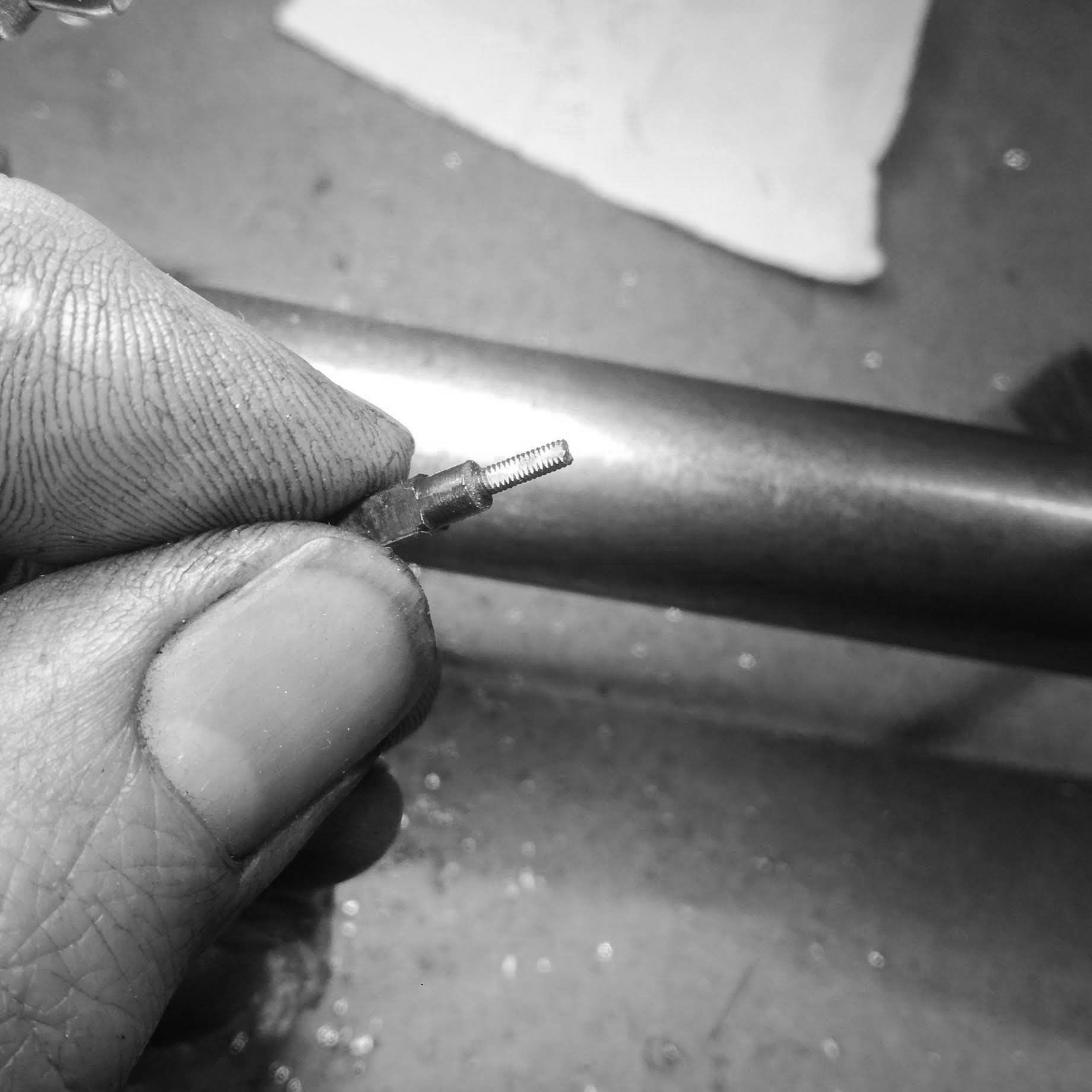
The crown tube threaded to the stem it will receive (the stem thread will need to be reduced so it doesn't protrude).
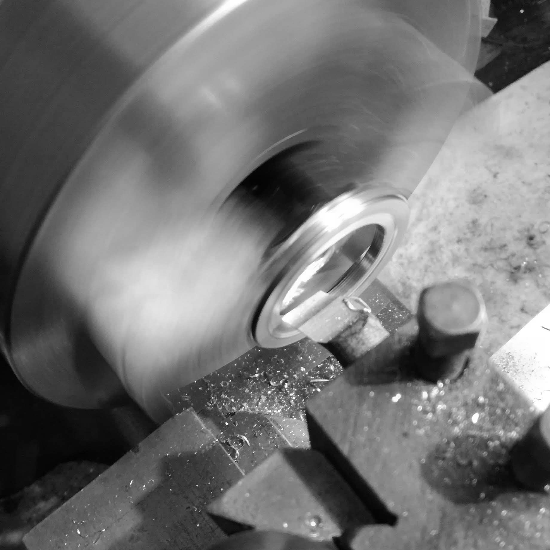
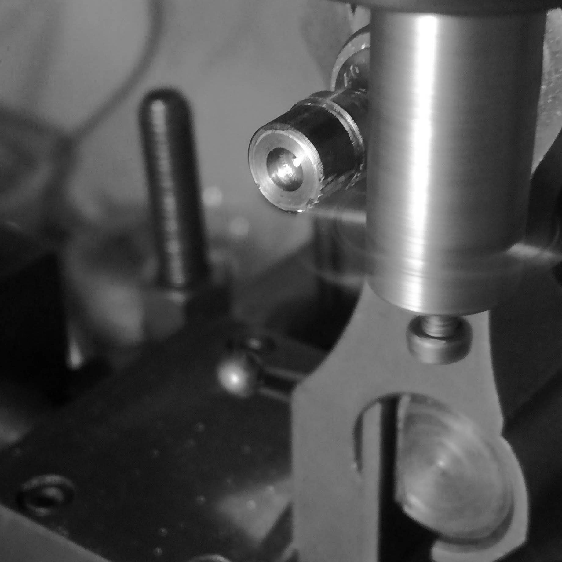
I start on the crown itself here. Drilling and boring the hole to accept the crown tube from the watch case.
Further boring the hole of the crown.
Testing the fit with the case crown tube, so that there is minimal axial play.
Turning the general outline of the interior portion of the crown.
Delimiting a range for the grip.
Drawing the groove angle on a piece of tracing paper.
Using the carbide grinder to cut the angle on the fly cutter.
Checking the angle of the cutter with the optical comparator.
Centering the dividing head with the spindle nose of the pantograph.
Before I start work on the stainless piece, I turn a brass blank to test the performance of the cutter.
The valleys of the cuts are a bit too rounded.
So the cutter tip is ground sharper.
Tested again on the brass blank.
Now onto the stainless crown. The depth of cut is achieved by cutting various ridges (3 or 4) and testing.
Initial cuts.
Checking the shape of the cuts using a mirror to see the work (and shine light on the crown).
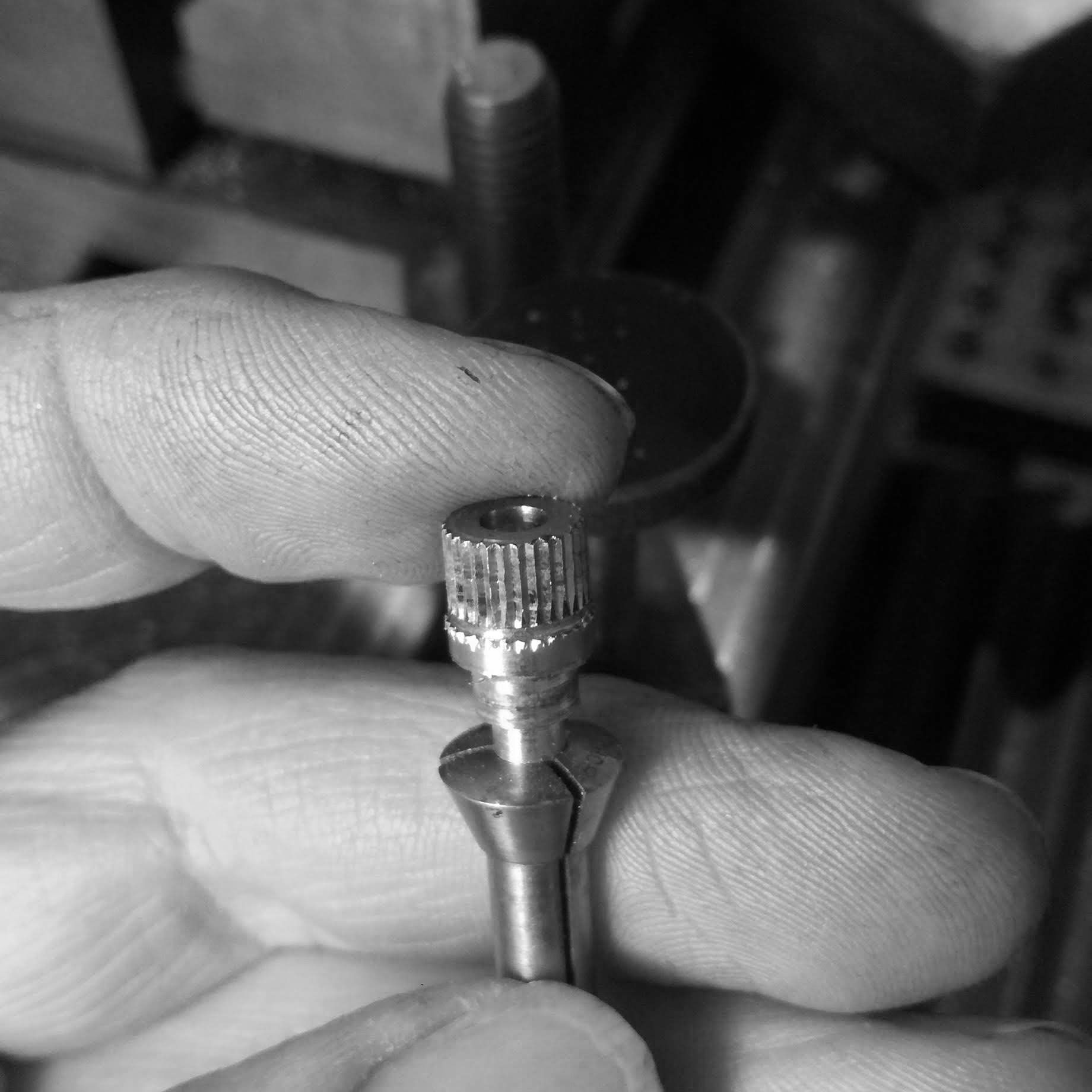
The first crown after indexing the 30 individual ridges of the grip.
Placed in the watchmaker's lathe to start cleaning up the internal face (which touches the case).
The crown is cleaned, and silver solder specks are used to weld the internal tube with the crown itself.
I insert the crown tube and then powered flux and the solder flakes.
So that the flux does not push the very light crown tube out during heating, I hold it in a toolmaker's clamp. Not the best setup, which will be addressed later.
The soldering did not flow as I expected, and I applied to much heat to make the silver flow.
This resulted in slightly distorting the crown tube, and the winding stem did not hold properly in the crown.
I decided to rethread the winding stem (to do this, I annealed the stem), and then rethreaded with a smaller thread diameter.
Here I am cutting another tap (one of a few to come!).
The winding crown hardened and tempered (was polished again after this).
The short tap. The fact that the principal shaft is still square, created a problem when tapping as we will see.
I heated the crown, and took the interior tube out, here I am cleaning away silver solder that remained inside.
Making a new stem tube for the crown.
Drilling the pilot hole.
As I tapped, it proceeded OK, but.
The tap broke in the last thread. The tap thread was eccentric from the square shaft portion, and led to torsion eccentrically from the tap itself, and broke. Everything is a learning process.
I try to save the stem tube by cutting away some of the portion of the back, to reveal the tap, and unscrew it.
After some patience, the broken tap is unscrewed out.
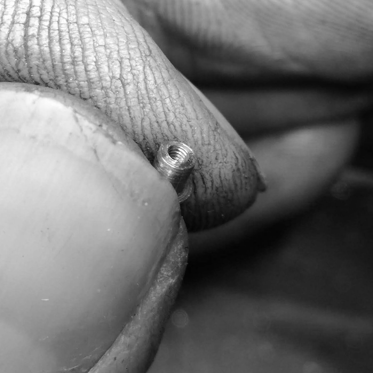
I check the threads, and they are still crisp, and good for use.
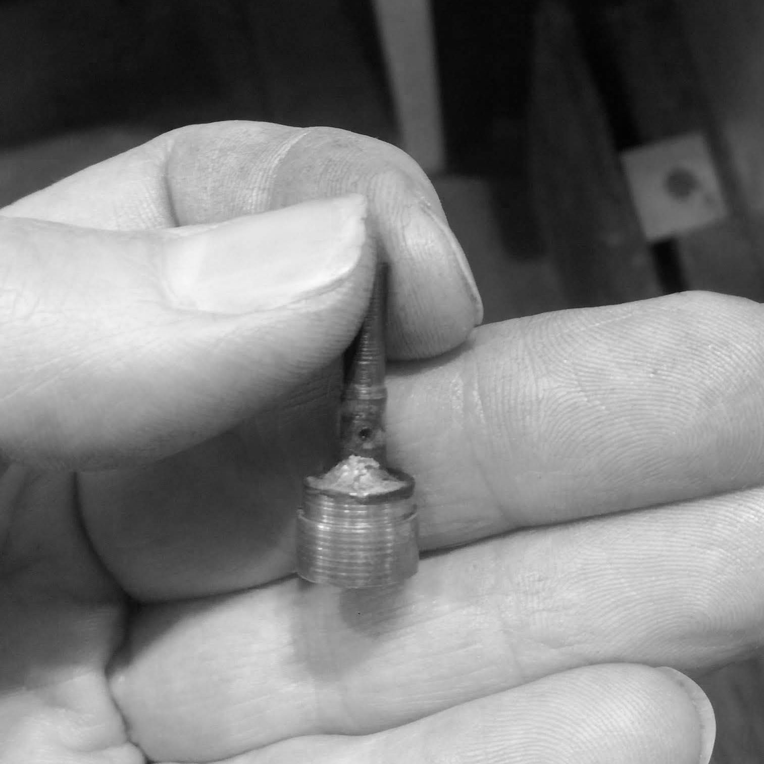
The stem tube and the stem.
I cut three recesses along the perimeter of the stem tube so that the soldier has more room to grip the part with the crown.
Before soldering the new stem tube, I decide to make a better work holding jig, so that I can more securely hold the stem for soldering. Here I use a piece of steel bar.
I cut a recess.
And then open.
A simple C clamp that does not use a screw to hold down the piece, thereby allowing me to apply downward pressure where I need more precisely.
The crown, set up with the stem tube ready for soldering.
I part off the crown from the work holding portion.
Face and elaborate the front of the crown.
The first fit of the crown on the watch case.
Polishing each grip recess with hard wood charged with diamond paste.
Using a depth stop on the collet to hold the crown, and address the depth the crown sits on the case tube.
This is the adjustable stop that allows one to grip a piece at a particular depth with each repeated insertion of the piece (convenient when checking often as I did here).
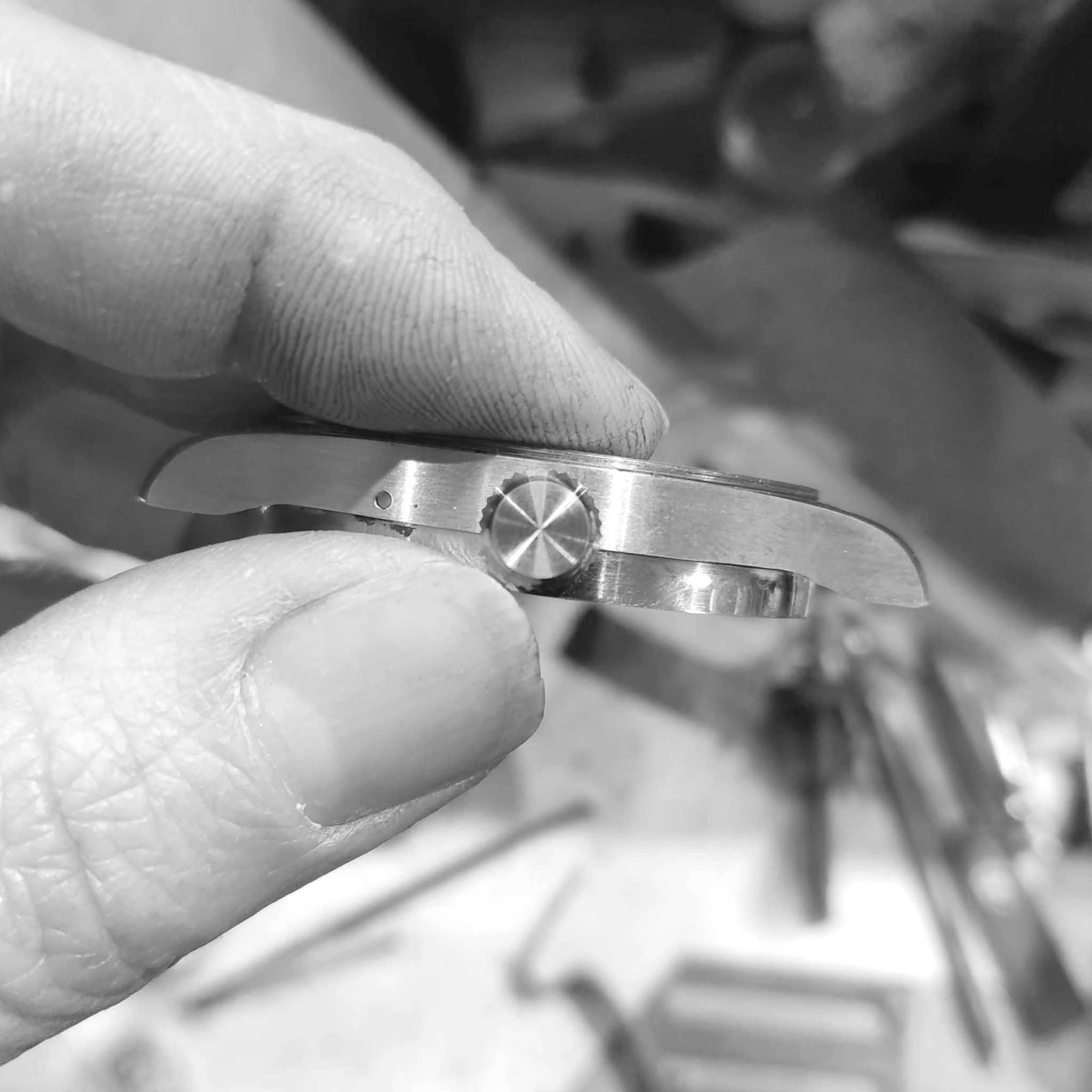
Further finishing the crown, this time, attached to the winding stem, and checking concentricity.
The brushed finish against the brushed finish of the case.
The polish on the fluted small bezel like contour I made on the crown.
Checked the winding and my attempt at a smaller than planned for crown was not successful. I could not easily wind the crown after a few turns.
Cutting a new crown holding stem for ease of work handling.
The parts of the new 316L crown to be used.
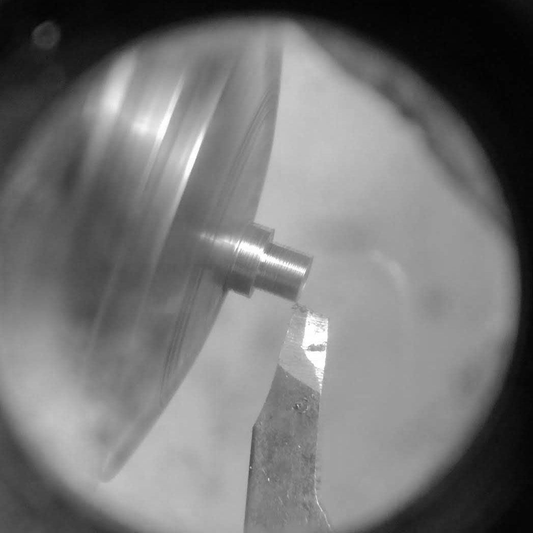
Turning the crown blank.
Soldering the blank to the holding stem.
A generous amount of solder is used to make sure that the torque during turning does not break the crown off the stem.
The crown blank was then put into the pantograph, and each ridge was then indexed again.
The cut crown.
Turning a new stem tube for the crown.
After having broken so many taps, I searched for an alternative and discovered this tool. With adjustable threading dies that allow tap and die sets to made.
I taped the new stem tube, however...
The tap broke, because I failed to adjust the diameter of the hole accordingly, so the tap broke at the very
I start on a new tube. However, the lesson is not learned just yet.
I continue to tap, but in order to save time, I used an older tap plug.
It was not centered at either end, and I quickly compensated by using a makeshift center on the chuck.
So the tap broke again.
So, I started from scratch, and cut a new blank for a tap. And proceeded to tap the plug successfully (process not shown as it is identical).
Testing the outer diameter of the stem tube on the case for eccentric play.
It turns OK and without too much play.
The stem tube is cut with a slitting saw as not to distort the very thin part.
Place in the crown.
Dressing the inner portion of the crown.
Polishing the crown grip ridges.
Creating a recess to do as much work as possible before parting the crown off.
Using the parting tool to create the recess.
Making space to work on the outer portion of the crown.
Using a hand graver (cylindrical), to create the convex flute on the outer portion of the crown.
After a lot of polishing and fine tuning (were on the watchmaker's lathe).
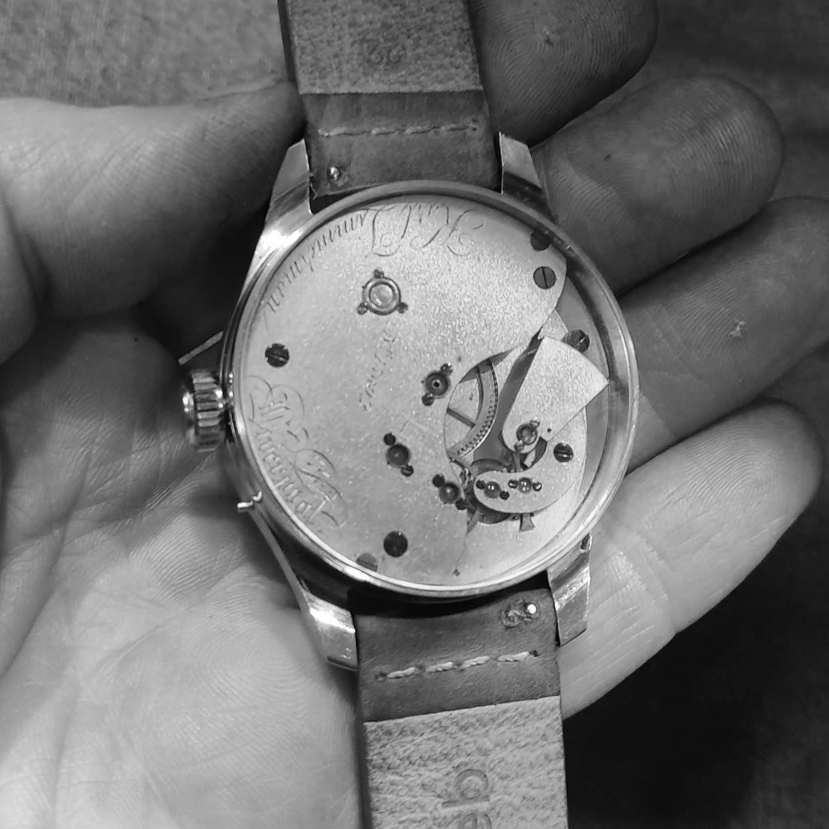
After testing (successful), the watch was assembled with an old dial to show you in person for your visit (mineral crystals fitted).
First time the nearly complete back is seen, with mineral crystal also.
Front view again.